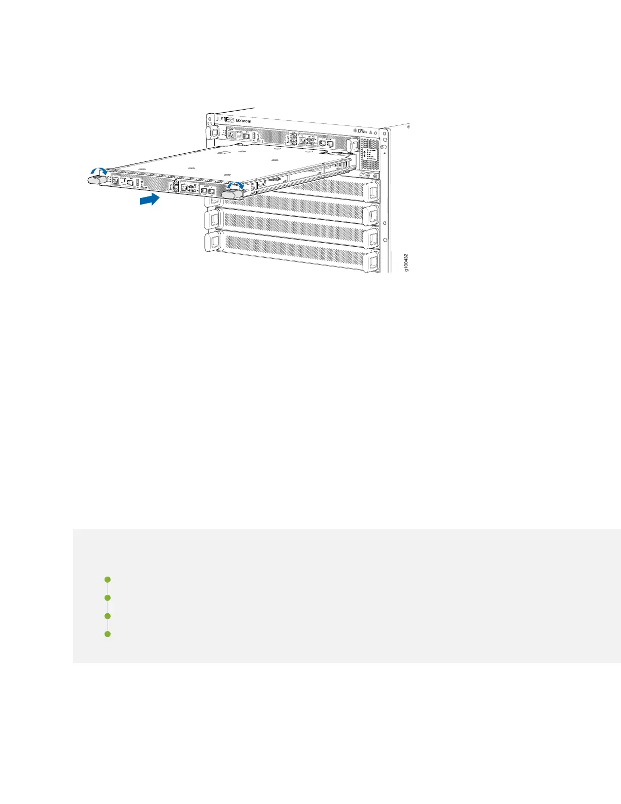
Figure 62: Routing and Control Board Installation
8. To verify that the RCB is functioning normally, check the PWR LED on its faceplate and the CONTROL
BOARDS LED on the status panel. Both LEDs should light steadily shortly after the RCB is installed. If
the PWR LED is blinking yellow, there might be insufficient power available.
You can also use the the show chassis environment cb command to verify that the RCB is online.
See “Power Requirements for MX10016 Components” on page 97 to ensure that you have adequate
power for the newly installed RCB.
Removing and Installing MX10016 Cooling System
Components
IN THIS SECTION
Removing an MX10016 Fan Tray | 163
Installing an MX10016 Fan Tray | 166
Removing an MX10016 Fan Tray Controller | 168
Installing an MX10016 Fan Tray Controller | 170
An MX10016 router has two independent, field-replaceable fan trays. Fan trays must be replaced within
the duration mentioned in Table 56 on page 163.
162