MULTICAL®603
KamstrupA/S∙Technicaldescription∙5512‐2029_A1_GB_06.2017
59
4.3 Mountingininletoroutlet
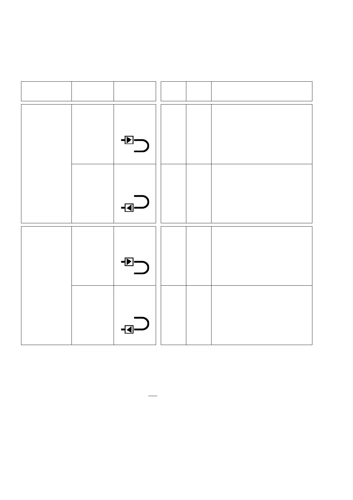
MULTICAL®603isconfiguredforflowsensormountedineitherforwardorreturnpipeduringinstallation.Inthe
display, the flow sensor position is indicated by a symbol; subjacent the A‐code of the configuration number is
programmedto3or4forflowsensorpositionininletandoutlet,respectively.
Thetablebelowindicatesinstallation
conditionsofheatmetersandcoolingmeters:
Formula k‐factor
A‐codeand
display
Hot
pipe
Cold
pipe
Installation
Heatmeter
E1=V1(t1‐t2)k
k‐factorfort1
andV1ininlet
A‐code=3
Display
V1and
t1
t2
Seeapplicationno.1inparagraph
7.1
k‐factorfort2
andV1in
outlet
A‐code=4
Display
t1
V1and
t2
Seealternativepositionofflow
sensorinapplicationno.1in
paragraph7.1
Coolingmeter
E3=V1(t2‐t1)k
k‐factorfort1
andV1ininlet
A‐code=3
Display
t2
V1and
t1
Seeapplicationno.1inparagraph
7.1
k‐factorfort2
andV1in
outlet
A‐code=4
Display
V1and
t2
t1
Seealternativepositionofflow
sensorinapplicationno.1in
paragraph7.1
4.4 EMCconditions
MULTICAL®603hasbeendesignedandCE‐markedaccordingtoEN1434ClassAandC(correspondingto
electromagneticenvironment:ClassE1andE2oftheMeasuringInstrumentsDirective)andcanthusbeinstalledin
bothresidentialandindustrialenvironments.
Allcontrolcablesmustbedrawnseparatelyandnotparallelto
e.g.powercablesorothercableswiththeriskof
inducingelectromagneticinterference.Theremustbeadistanceofmin.25cmbetweensignalcablesandother
installations.