MULTICAL®603
118
KamstrupA/S∙Technicaldescription∙5512‐2029
A1_GB
06.2017
8.2 Flowsensorwithreedorrelayswitchoutput(ConnectiontypeL)
Thereedswitchoutputistypicallyplacedasapick‐upunitonvanewheelorWoltmannmeterswheretherelayswitch
output is typically found on magnetic inductive flow sensors. Flow sensors connected to input V1 on the screw
terminals10(+)and11(‐)andinputV2on
thescrewterminals10(+)and69(‐).Screwterminal9isnotusedinthis
application.
Theleakagecurrentintheswitchmustnotexceed1µAinOFFstate,andtheresistanceintheswitchsetmustnot
exceed10kΩinONstate.
Itmustbe
ensuredthatMULTICAL®603isc onfiguredwithaCCC‐codewhosepulsefigure(imp./lorl/im p.)matches
theconnectedflowsensors.
Example:CCC=011isusedforameterwithreedpulseswith10l/imp.andamaxflowof1…30m³/h.
8.3 Flowsensorwithtransistoroutput(Connectiontype7‐8‐C‐J)
Typically,theflowsensoroutputisconstructedasanoptocouplerwithBJTorFETtransistoroutput.Flowsensors
connectedtoinputV1onthescrewterminals10(+)and11(‐)andinputV2onthescrewterminals10(+)and69(‐).
Screwterminal9 isnot
usedinthisapplication.
Theleakagecurrentinthetransistormustnotexceed1µAinOFFstate,andthevoltageabovethetransistormustnot
exceed0.4VinONstate.
Itmustbeensuredtha tMULTICAL®603isconfiguredwithaCCC‐codewhosepulsefigure(imp./lor
l/imp.)matches
theconnectedflowsensors.
Example:CCC=201isusedforanelectronicmeterwith1l/imp.andq
p
=4…150m³/h.
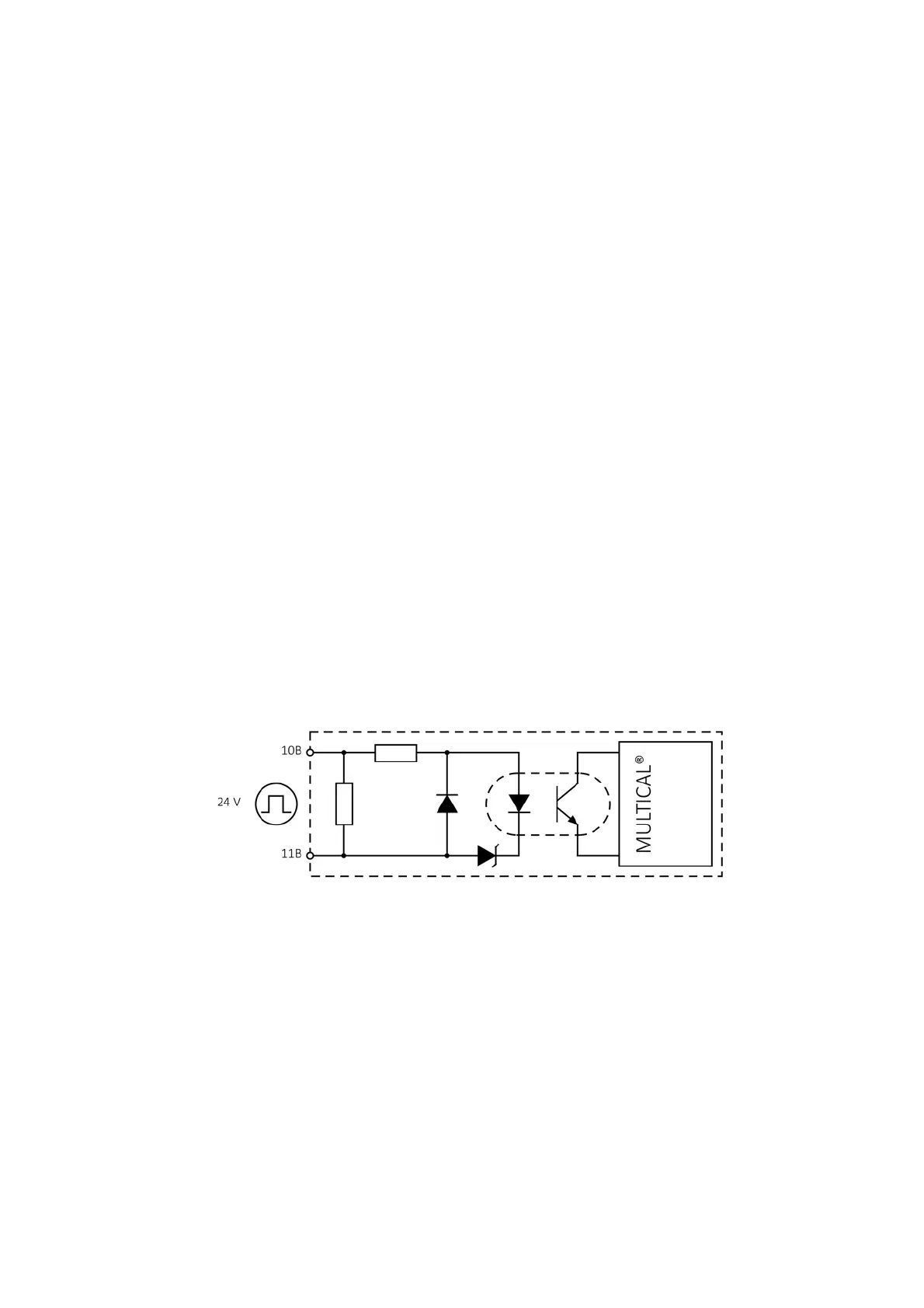
8.4 Flowsensorswithactive24Vpulseoutput(ConnectiontypeP)
Flowsensorswithactive24VpulseoutputfromforexampleSiemens,KrohneorABBcanbedirectlyconnectedto
MULTICAL®603type603‐G.Atthesametime,thistypeispreparedforconnectionof4‐wiretemperaturesensors.
Theconnectioniscarriedoutasshowninthefigurebelow.
Forfurtherexamples,see8.4.1.
Technicaldata:
Pulseinputvoltage 12…32V
Pulsecurrent Max12mAat24V
Pulsefrequency Max128Hz
Pulseduration Min.3ms
CablelengthV1 Max100m
(Drawnwithmin.25cmdistancetoothercables)

 Loading...


