MULTICAL®603
KamstrupA/S∙Technicaldescription∙5512‐2029_A1_GB_06.2017
57
4 Installation
4.1 Installat ionrequirements
PriortoinstallationofMULTICAL®603inconnectionwithflowsensors,theheatingsystemshouldbeflushedwhilea
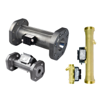
fittingpiecereplacesthemeter.IfULTRAFLOW®ismounted,theadhesivewafersareremovedfromthemeter'sinlet
andoutlet,andtheflowsensorismountedwithcouplings/flanges.Newfibregasketsin
originalqualitymustbeused.
IfothercouplingsthantheoriginalonesfromKamstrupA/Sareused,youmustmakesure thatthethreadedlengths
ofthecouplingsdonotpreventpropertighteningofthesealingsurface.
Thepositioningoftheflowsensorininletoroutletcanbeconfigured
inthecalculatorbeforecommissioning,see
paragraph6.3aboutSETUPloop.Theflowdirectionisindicatedbyanarrowontheflowsensor.
Inordertoavoidcavitation,thebackpressureatULTR AFLOW®(thepressureattheflowsensoroutlet)musttypically
beminimum1baratqpandminimum2
baratqs.Thisappliestotemperaturesuptoapprox.80
o
C.
Whentheinstallationhasbeencompleted,waterflowcanbeturnedon.Thevalveontheflowsensor'sinletsidemust
beopenedfirst.
ULTRAFLOW®mustnotbeexposedtolowerpressurethantheambientpressure(vacuum).
Permissibleoperatingconditions
Ambienttemperature: 5…55C(indoors).Max30Cfor
optimumbatterylifetime.
Mediumtemperatureofheatmeter: 2…130Cwithcalculatormountedonawall
15…90CwithcalculatormountedonULTRAFLOW®
Mediumtemperatureofcoolingmeter: 2…130Cwithcalculatormountedonawall
Mediatemperatureofheat/coolingmeter: 2…130Cwithcalculatormountedona
wall
SystempressureULTRAFLOW®: 1.0…16barforthreadedmeters
1.5…25barforflangemeters
Electricalinstallation s
MULTICAL®603isavailablewitheither24VAC/VDCor230VACsupplymodules.Thesupplymodulesareconnected
tomainsusingtwo‐wirecablewithoutprotectiveearth.
Useastrongconnectioncablewithan
outerdiameterofmax5‐8mmandensurecorrectcablestrippingandcable
reliefinthemeter.Itmustbeensuredthattheentireinstallationcomplieswithcurrentregulations,thesupplycable
tothemetermustneverbeprotectedbyalargerfusethanpermitted.Incaseofdoubt,
itisrecommendedtotake
advicefromanauthorisedelectrician.
For installation in Denmark, SIK‐message 27/09, “Installation to mains connected equipment for registration of
consumption” applies to meters connected to both 230 VAC and 24 VAC powered via safety transformer, see
paragraph10.9.
Service
Neitherweldingnorfreezingisallowed
whileULTRAFLOW®ismounted.Beforestartingsuchwork,ULTRAFLOW®must
bedismounted.Ifthemeterismainssupplied,thesupplymustbeswitchedoff.
Inordertofacilitatethereplacementofthemeter,closingvalvesshouldalwaysbemountedonbothsidesoftheflow
sensor.
Undernormaloperatingconditions
nopipestrainerisrequiredinfrontofthemeter.
 Loading...
