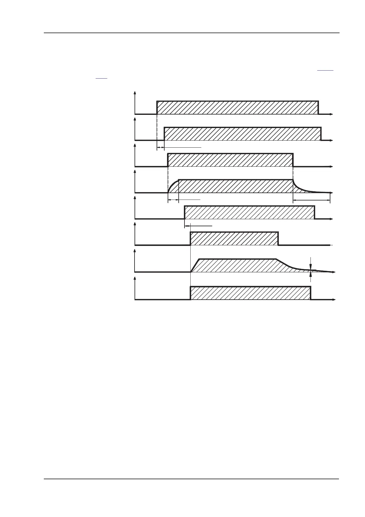
6.7.1 Behavior in standard operation
The behavior of the servo amplifier always depends on the current setting of a number of
different parameters (e.g., ACTFAULT, VBUSMIN, VELO, STOPMODE, etc.; see online
help). The diagram below illustrates the correct functional sequence for switching the
servo amplifier on and off.
Devices which are equipped with a selected “Brake” function use a special sequence for
switching off the output stage (ð p.29).
The safety function STO can be used to switch off the drive, so that functional safety is
ensured at the drive shaft (ð p. 37).
S300 Instructions Manual 33
Kollmorgen 02/2017 Technical description
SW-ENABLE
&
HW-ENABLE
n
U
U
> 100ms
STO-ENABLE
BTB/RTO
L1,L2,L3
24V
< 15s (Boot-time)
U
U
U
U
5
t
t
VELO
t
t
5...8 min.
t
t
t
t
~500ms
Motor speed
Power Stage
enable (inter
nal)
DC bus link
 Loading...