8.13.2 Connection to stepper motor controllers (step and direction)
You can connect the servo amplifier to a third-party stepper-motor controller. Parameter
setting for the slave amplifier is carried out with the aid of the setup software (electronic
gearing). The number of steps can be adjusted, so that the servo amplifier can be
adapted to match the step-direction signals of any stepper controller. Various monitoring
signals can be generated.
Observe the frequency limit!
Using an A quad B encoder provides better EMC noise immunity.
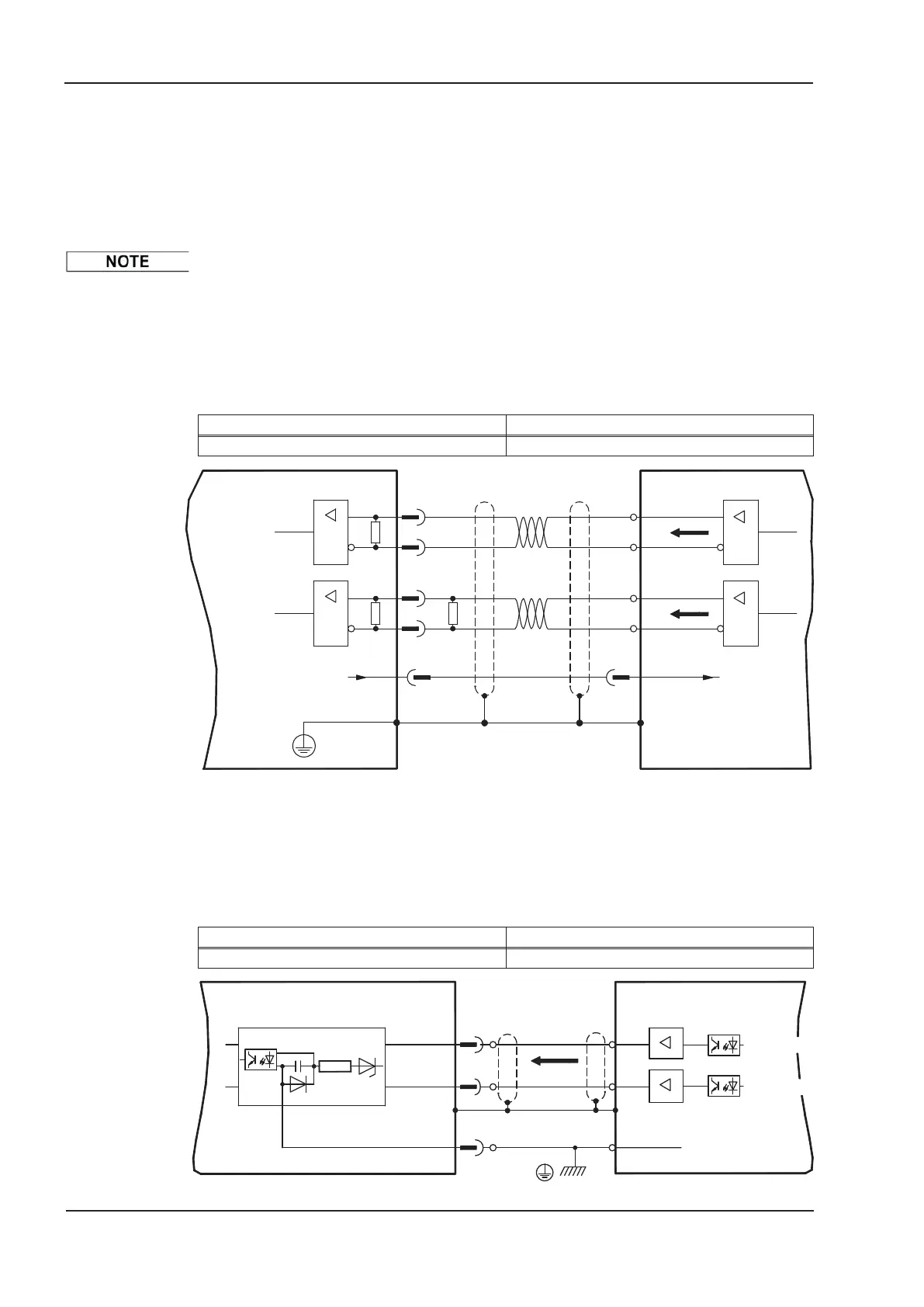
8.13.2.1 Step/Direction 5V, 1.5 MHz (X1)
Wiring of the servo amplifier (SubD connector X1) to a stepper-motor controller witha5V
signal level. Frequency limit: 1.5 MHz
Type GEARMODE
Step/Direction 5V 27
8.13.2.2 Step/Direction 24V, 100 kHz (X3)
Wiring of the servo amplifier to a stepper-motor controller with a 24 V signal level. Used
are the digital inputs DIGITAL-IN 1 and 2 on connector X3.
Frequency limit: 100 kHz
Type GEARMODE
Step/Direction 24V 1
88 S300 Instructions Manual
Electrical installation 02/2017 Kollmorgen
Master
2
0V
RS 485
RS 485
10k
120
15
8
13
5
X1
GND
RS 485
RS 485
120
pulse
direction
+5V ref. to GND
direction
pulse
S300
DIGITAL-IN2
DIGITAL-IN1
4
8
9
DGND
X3
GND
Master
X4
pulse
direction
+24V ref. to GND
direction
pulse
S300
 Loading...