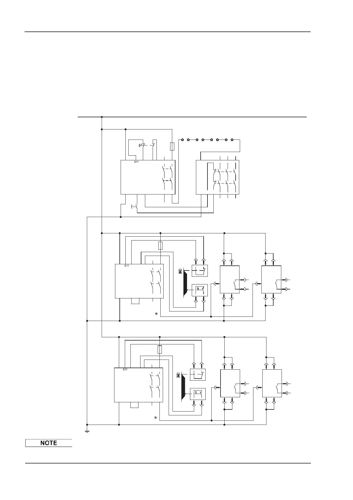
6.9.8.2 Control circuit
The example shows a circuit diagram with two separated work areas connected to one
emergency stop circuit. For each work area individually "safe stop" of the drives is
switched by a protective screen.
The safety switch gears used in the example are manufactured by Pilz and fulfill at least
the PL d acc. to ISO 13849-1. Further information to the safety switch gears is available
from Pilz. The use of safety switch gears of other manufacturers is possible, if these also
fulfill the SIL CL 2 according to IEC 62061 and PL d according to ISO 13849-1.
Consider the wiring instructions on page 39.
42 S300 Instructions Manual
Technical description 02/2017 Kollmorgen
24
12
0V
K4
S6
23
STO-Enable
23
24
S21
S34A2
A1
S12
14
S22 13
F3
A2 S34 14
S5
11
STO-Enable
24
S4
23
K3
+24VDC
S21A1 S12 S22 13
F2
23
S3
11
12 12
X4
1
X4
1
1
2
2
1
2
2
5
X4
X4
BTB
4
3
X4
2
1
24
5
BTB
4
3
X4
5
X3
X4
X4
BTB
4
3
X4
2
1
5
BTB
4
3
X4
X3
12
2
1
X4
X3
2
1
X4
12 12
X3
*
*
BTB
A1
A2
K1
13
14
Reset
-S1
A2 S12 S34 2414
S22
E-Stop
PNOZ S3
A1
-S2
S21S12 2313
F1
K2
BTB
12
Y2Y1
BTB
3
BTB
4
PNOZ S3
PNOZ S3
S12
S12
contactor
Mains
Drive 1 Drive 2
Drive 5Drive 4
Emergency-stop circuit
acc. to ISO 13849-1 PL e
Safe stop acc. to ISO 13849-1 PL d, single channel, group 1 for 2 drives
Safe stop acc. to ISO 13849-1 PL d, single channel, group 2 for 2 drives

 Loading...


