Technical data
Operating manual for INVEOR α | DOC01539818 - 0004 | 2017-01 | V2.0 EN 119
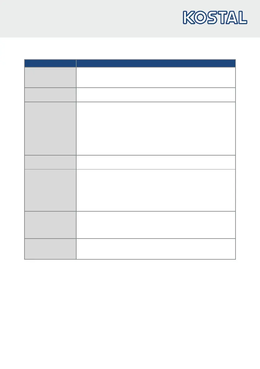
8.1.2 Specification of interfaces
Digital inputs 1 – 2 -
-
-
Switching level low < 5 V / high > 15 V
Imax (at 24 V) = 3 mA
Rin = 8.6 kOhm
Hardware approval
for input
-
-
Switching level low < 3 V / high > 18 V
Imax (at 24 V) = 8 mA
Analogue inputs 1 -
-
-
-
In +/- 10 V or 0 - 20 mA
In 2 - 10 V or 4 - 20 mA
10-bit resolution
Tolerance +/- 2 %
Voltage input:
- Rin = 10 kOhm
Current input:
- Working resistance = 500 Ohm
Digital outputs 1 -
-
Short-circuit proof
Imax = 20 mA
Relay 1 1 changeover contact (NO/NC)
Maximum switching power *
-
at ohmic load (cos ϕ = 1): 5 A at ~ 230 V or = 30 V
-
at inductive load (cos ϕ = 0.4 and L/R = 7 ms): 2 A at ~ 230 V or = 30 V
Maximum reaction time: 7 ms ± 0.5 ms
Electric life: 100 000 switching cycles
Power supply 24 V -
-
-
-
Auxiliary voltage U = 24 V DC
Short-circuit proof
Imax = 100 mA
external feeding of 24 V possible
Power supply 10 V -
-
-
Auxiliary voltage U = 10 V DC
Short-circuit proof
Imax = 30 mA
Tab. 6: Specification of interfaces
* in accordance with UL-61800-5-1 the maximum allowed is 2 A!
 Loading...