Technical data
122 Operating manual for INVEOR α | DOC01539818 - 0004 | 2017-01 | V2.0 EN
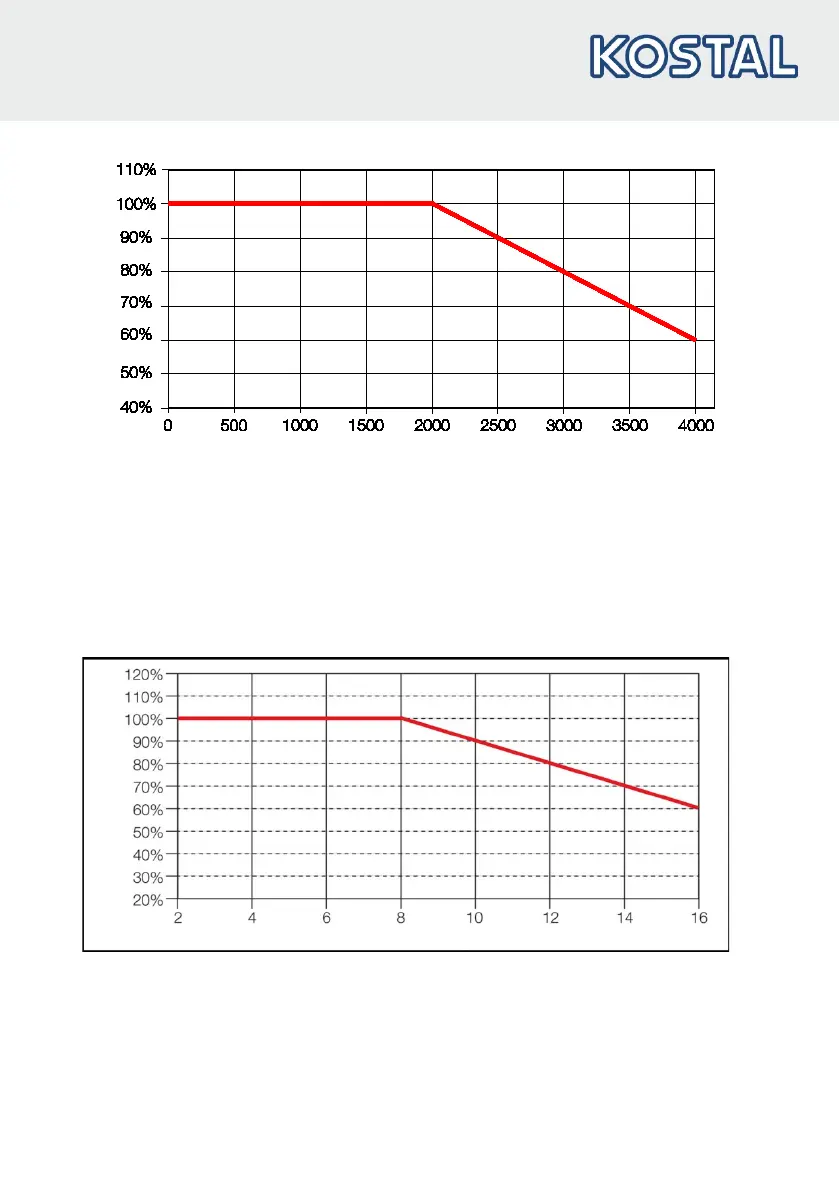
Fig.: 34 Derating of maximum input voltage as a result of installation altitude
8.2.3 Derating due to switching frequency
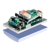
The following diagram shows the output current, depending on switching frequency. To limit the
thermal losses in the drive controller, the output current must be reduced.
Note: The switching frequency is not reduced automatically!
The max. output values can be determined from the following characteristic curve.
Fig.: 35 Derating of maximum output current as a result of switching frequency



 To Next Page