Installation
46 Operating manual for INVEOR α | DOC01539818 - 0004 | 2017-01 | V2.0 EN
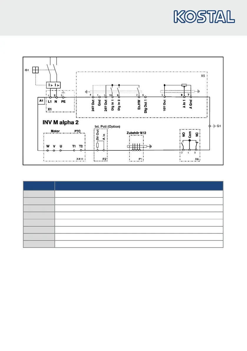
3.4.5 Connection diagram
Fig.: 18 Connection diagram
Characters Explanation
A1 Drive controller type: INVEOR M α 2 (1~ 230 V)
M6 grounding screw (connection for residual currents > 3.5 mA)
RS485 internal programming interface (M12 plug) (optional)
Internal potentiometer (optional)
Q1 Motor protection switch or load break switch (optional)
Mains terminals
X411 Motor and PTC terminals
Digital/analogue inputs and outputs
The drive controller is ready once a 230 V AC mains supply has been activated (on terminals
L and N) or a 325 V DC mains supply has been activated (on terminals L and N).