Installation
Operating manual for INVEOR α | DOC01539818 - 0004 | 2017-01 | V2.0 EN 43
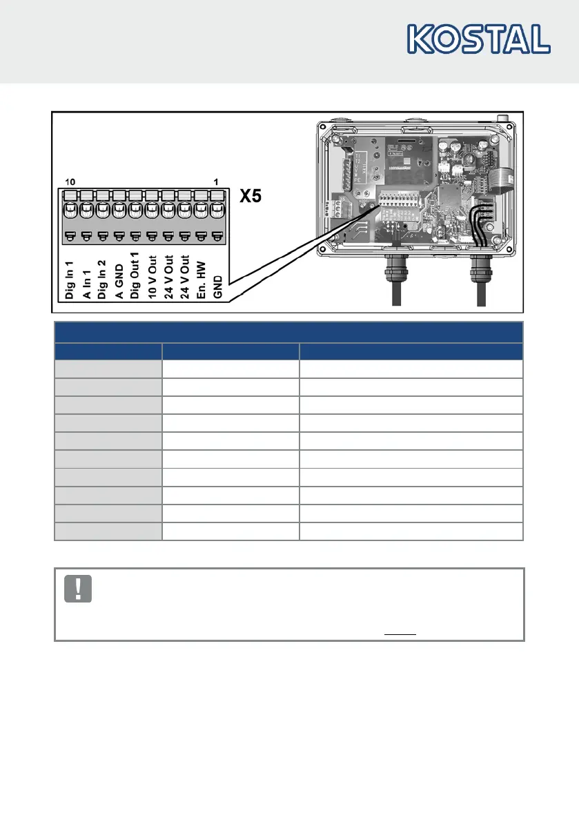
Control connection X5
1 GND (ground) Ground
2 En HW (enable) Enable hardware
3 24 V Out Int. power supply
4 24 V Out Int. power supply
5 10 V Out For ext. voltage divider
Fault message (parameter 4.150)
Target value enable (parameter 1.131)
If a control line is not attached, a bridge must be connected between "24 V Out" and "En. HW".
When the bridge is connected, the drive controller's output stage is always enabled.