Audio Synchronizer Module
Block Diagram
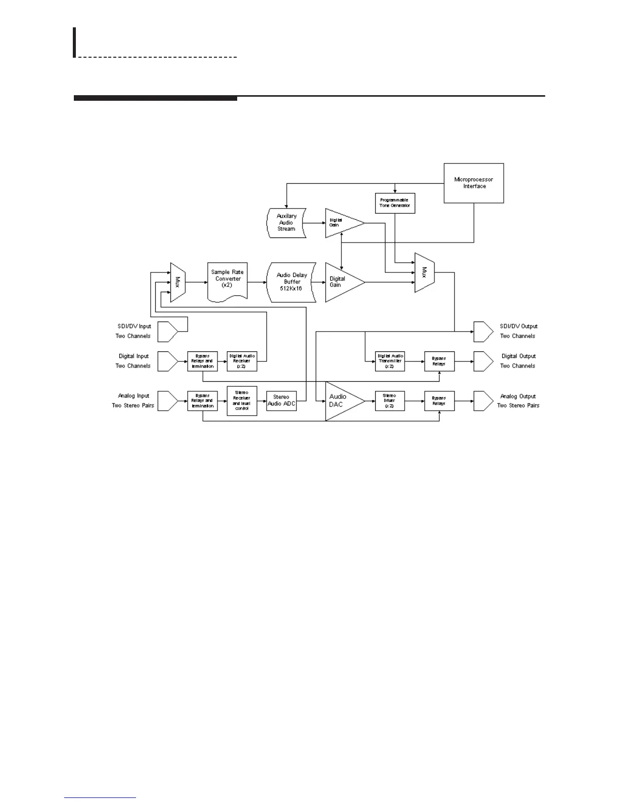
Figure 1
Analog Input
The analog input is received through a 12-position terminal block. Each signal has
connections for positive, negative and ground.
The bypass relays allow the analog input signal to be routed to the analog output
signal in the absence of power to the unit. The termination relays allow for user-
specified input termination configurations, grouped by stereo-pair. The supported
options are balanced or unbalanced, and 600Ω or high impedance (>20KΩ) inputs.
Stereo Receiver and Level Control
The receiver converts balanced analog audio to single-ended analog audio, and scales
them to the internal working voltage range of +/- 3.75V. The maximum input level
accepted by the receiver is +24 dBu.
dBu = 20 log (E / 0.7746), where E is the RMS voltage. Peak voltage = sqrt(2) *
RMS voltage for a sine wave
The stereo level control is to allow for different studio operating levels for the analog
audio. The In Op. Level parameter, in conjunction with the Headroom parameter, sets
the gain of this stage. The sum of the headroom and level cannot exceed the
operational levels of the input, which are +24dBu. Typical values for level and
headroom are 0dBu and 18dB, respectively.
88
DPS-475/575 Service Manual