Appendix C
board with connector NCN1 on the main board (see the previous diagram of the
main board, and the following diagram of the DV I/O Option board, for
positioning). Gently press the DV I/O Option board onto the connector. Be sure
to apply pressure evenly across the connector to prevent the pins from bending or
breaking.
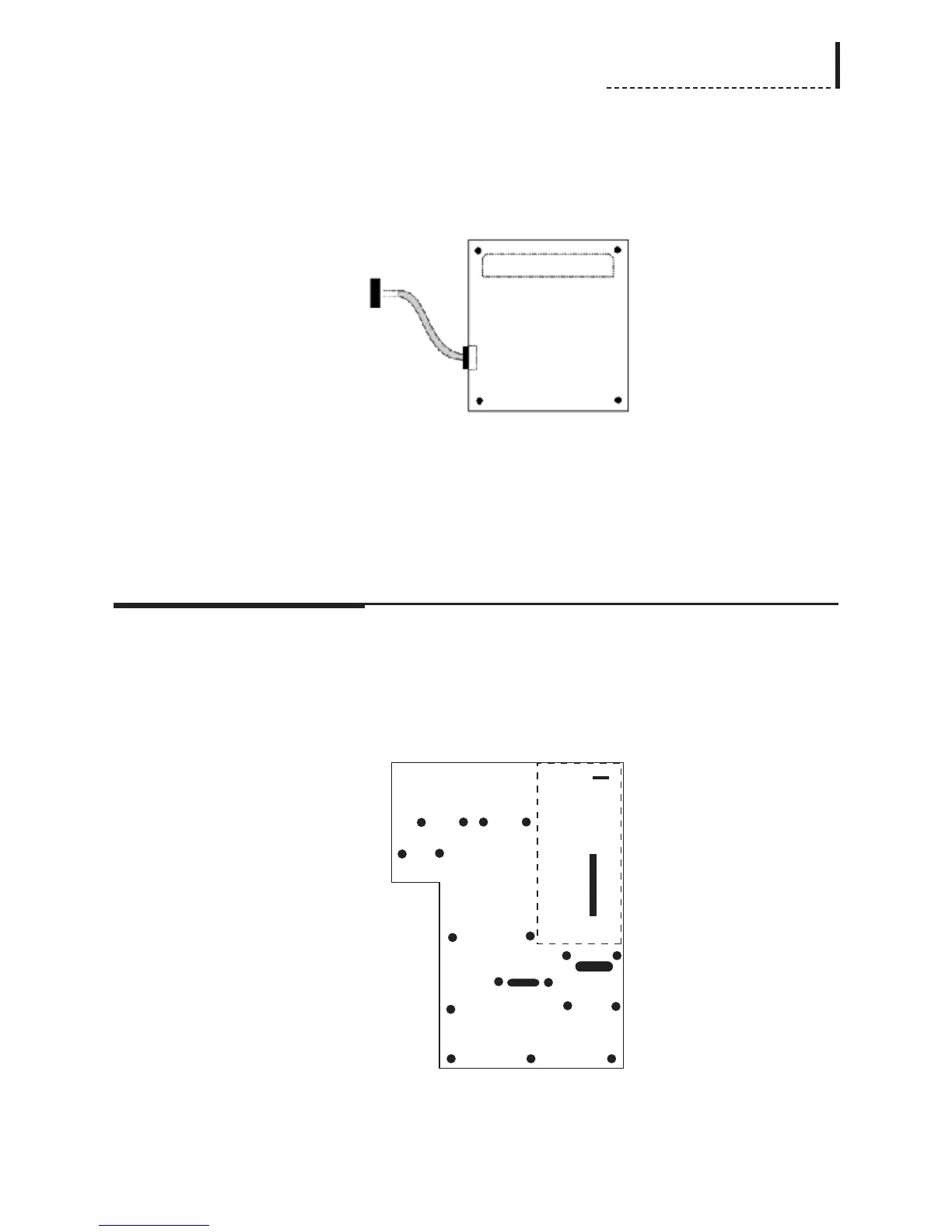
DV I/O Option Board (Top View)
The dashed lines in the above diagram of the DV I/O Option board indicate the
position of the connectors on the bottom of the board.
6. Use the supplied screws (part number 751-010) to secure the DV I/O Option
board to the standoffs in the main board.
Installation of Audio Synchronizer Module
1. There are four screws that must be removed from the main board of the unit, and
replaced with the four supplied standoffs (part number 762-170). [Note: these
standoffs may be pre-installed on the main board of your unit.] These screws are
designated with * in the following diagram:
The dashed rectangle indicates the position into which the Audio Synchronizer
Module will be installed.
197