Appendix C
10. Use the two supplied jackscrews (part number 762-142) to secure the DB25
connector to the chassis of the unit.
11. Plug the analog audio terminal blocks back into their mounting connectors on the
Audio Synchronizer Module.
Removal of Audio Synchronizer Module
If you must remove the Audio Synchronizer Module from the unit (for example, to
install the DV I/O Option board), the following instructions will walk you through the
process properly and safely.
1. Remove the two jackscrews that secure the DB25 connector on the Audio
Synchronizer Module to the chassis of the unit.
2. If the terminal blocks for analog audio are plugged into their mounting
connectors on the Audio Synchronizer Module, remove them.
3. Remove the four screws that secure the Audio Synchronizer Module. See the
diagram of the main board in the “Installation of Audio Synchronizer Module”
section of this Appendix to locate the correct screws.
4. Gently lift the Audio Synchronizer Module from it’s connector, to disconnect it
from the main board. Be sure to lift the board off evenly, to prevent the connector
pins from bending or breaking. Inspect the connectors on the Audio Synchronizer
Module and main board to ensure that all pins are straight.
5. Once the connector is completely free, you can pull the audio board out to free it
from the back panel. Be sure to store the board in a protective bag to protect it
from static electricity.
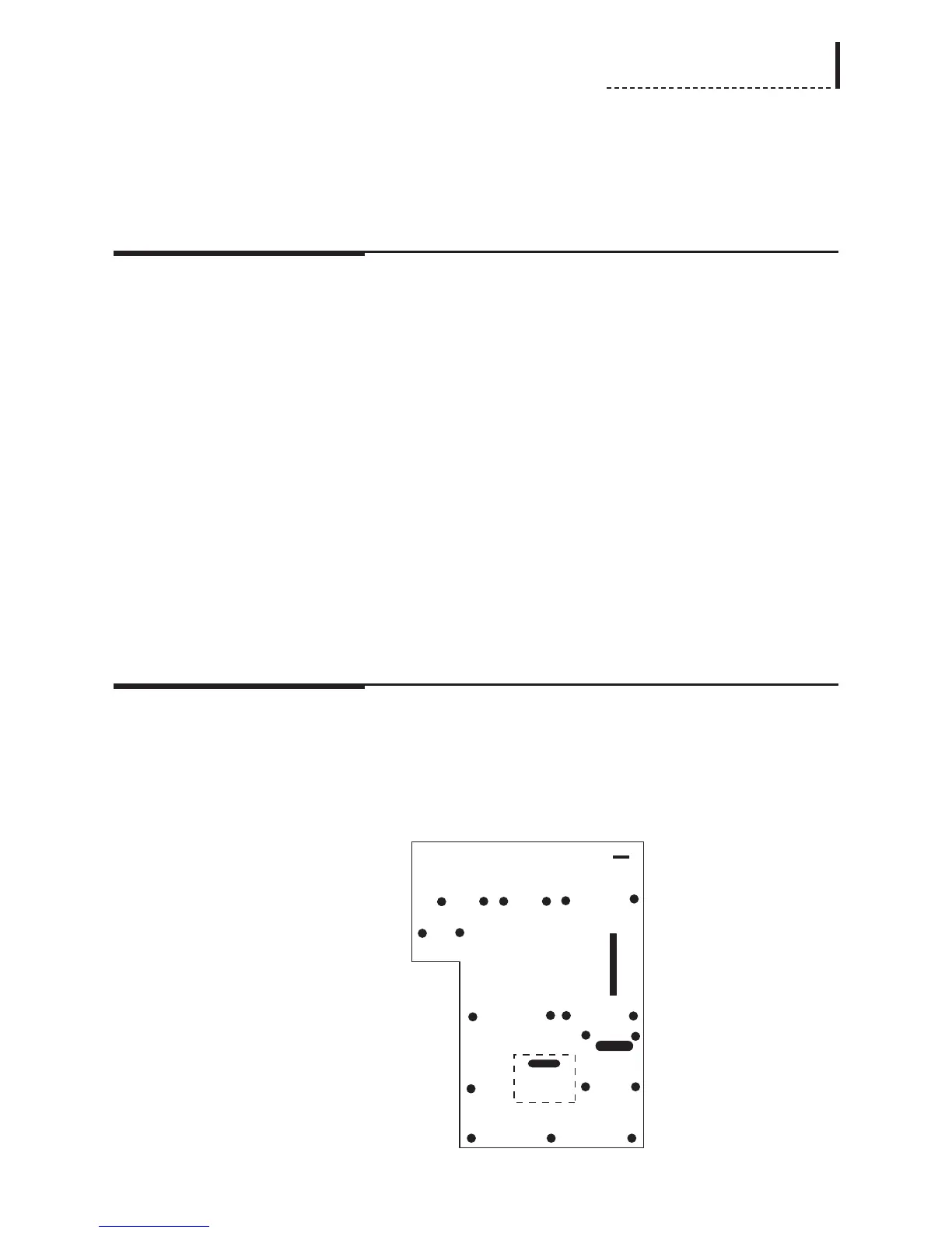
Installation of Animated Logo Option Board
1. The dashed rectangle in the following diagram indicates the position into which
the Animated Logo Option board will be installed. Two standoffs (part number
762-2300), into which screws will secure the board, are pre-installed into the
main board of the unit and are designated with * in the diagram:
DPS-475/575
199