Chapter 13:
Theory of Operations
Both formats are available concurrently on the breakout cable. For the BNC output,
the operator may select AES Consumer or SPDIF levels.
Stereo Audio DAC and Level Control
The stereo audio DAC is contained within the same device as the ADC. This device
has a built-in analog level control to adjust for output headroom of the user
installation. The DAC shares a common output sample rate with the ADC.
Analog Output
The analog output consists of balanced audio drivers. The drivers are configured for
output impedance of 10Ω, and are capable of driving 600Ω input impedance loads to
levels of +24dBu.
Microprocessor Interface
The microprocessor interface allows communication with the control microprocessor.
The interface is a parallel interface, to map the audio card into the microprocessor's
memory space. The format for the interface will be defined later in this document.
Connectors and Signals
External Analog Audio Connector
The two 12-position terminal blocks are divided into four sections of three terminals.
The left terminal block is channel 1 and the right terminal block is channel 2. The
positions of the terminal block are labelled (from left to right), IN1+, IN11-, IN1G,
IN2+, IN2-, INSG, OUT1+, OUT1-, OUT1G, OUT2+, OUT2-, and OUT2G.
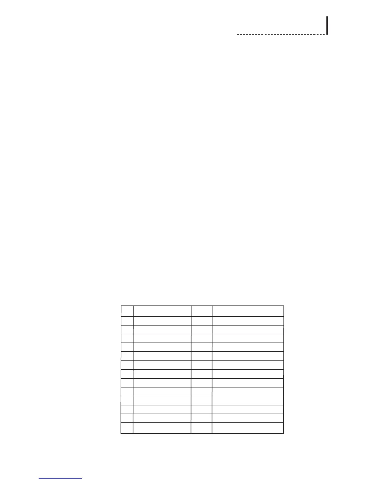
External Digital Audio Connector
The digital audio connector is a 25 pin D-Sub-Miniature connector. An audio
breakout cable allows for the XLR and BNC connectors for the different AES/EBU
standards, with pin assignments given in the table.
Pin Function Pin Function
1NC 14 NC
2 XLR_AES2_OUT_1 15 BNC_AES2_OUT_C
3 XLR_AES2_OUT_3 16 BNC_AES2_OUT_S
4 XLR_AES2_OUT_2 17 NC
5 XLR_AES2_IN_1 18 BNC_AES2_IN_S
6 XLR_AES2_IN_3 19 BNC_AES2_IN_C
7 XLR_AES2_IN_2 20 NC
8 XLR_AES1_OUT_1 21 BNC_AES1_OUT_S
9 XLR_AES1_OUT_3 22 BNC_AES1_OUT_C
10 XLR_AES1_OUT_2 23 NC
11 XLR_AES1_IN_1 24 BNC_AES1_IN_S
12 XLR_AES1_IN_3 25 BNC_AES1_IN_C
13 XLR_AES1_IN_2
91