Chapter 15:
Test/Alignment Procedures - Audio
DPS-470 De-Tuned Reference
The DPS-470 de-tuned reference is to provide a composite video source with a clock
reference significantly different than that of the test bench DPS-475. This is
accomplished by removing the top cover of the DPS-470 and adjusting the pot GRV1
full to the right position. The top cover may be replaced after the adjustment is made.
If a DPS-470 unit is not available, you can substitute any composite video source that
has a frequency reference (colour sub-carrier) well outside the NTSC/PAL
specification. This is primarily used to test the Auto Track feature. You will also need
the DPS-475 Test Program running on the Audio Precision test station.
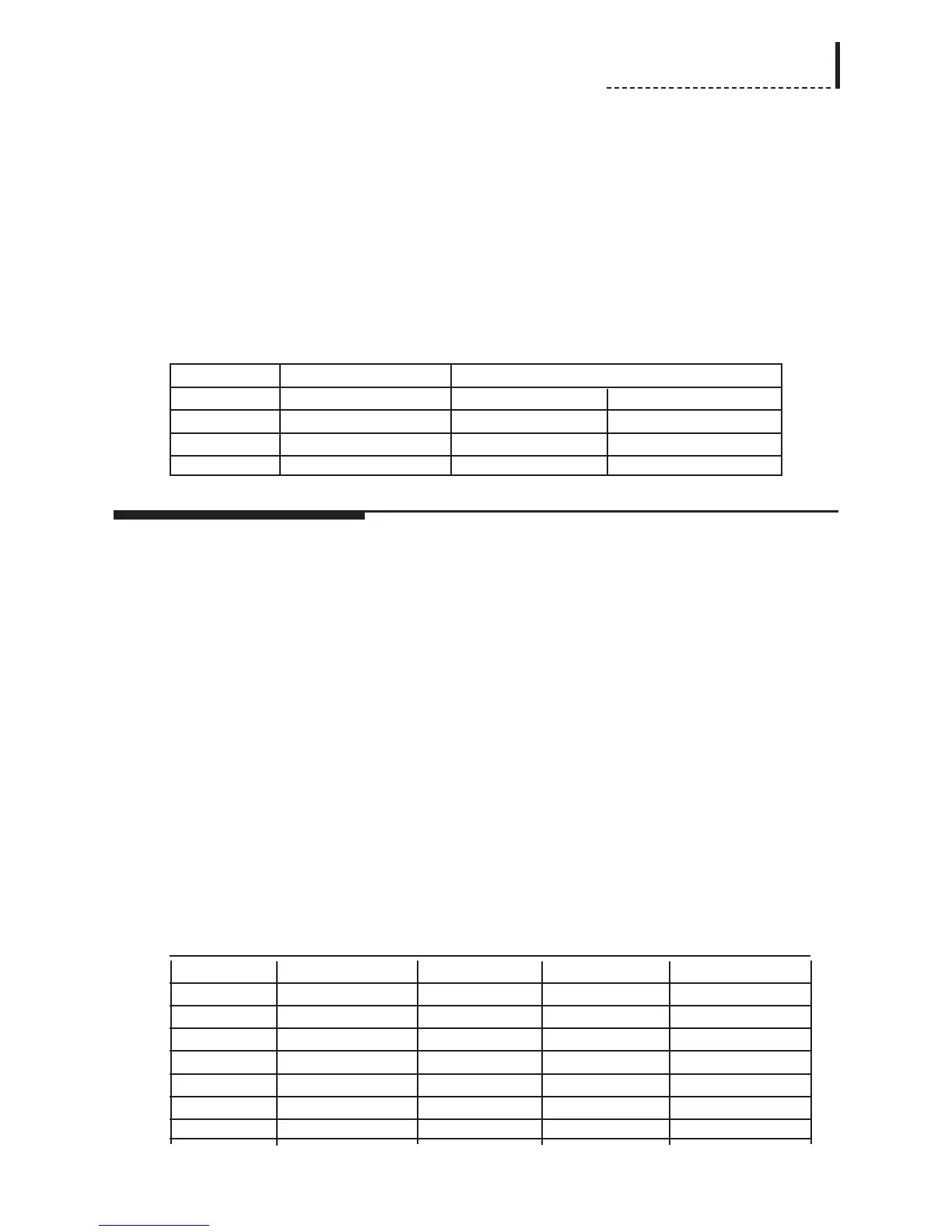
Audio Precision
Generator Analyzer
Tone 1KHz
Level +18dBu Units in dBu Units in dBu
Impedance 40Ω 600Ω 600Ω
Configuration Balanced - GND XLR-Balanced XLR-Balanced
Visual Inspection and Power-Up Test
The purpose of this test is to ensure that the board is capable of being tested and will
not cause problems with the rest of the system.
Visual Inspection
Visually check that all components on the Audio Option module have been installed
properly. This check should include the following points as a minimum:
• Verify that all necessary components have been installed.
• Verify correct orientation on polarized devices and integrated circuits.
• Search for the presence of solder balls and shorts.
Installation of the card
Install the audio card in the DPS-475 chassis, as detailed in Appendix C, “Installation of Hardware Options.”
Apply Initial Power
Apply power to the chassis, using the main AC power switch. Check the audio card
for signs of overheating. Verify that power supplies to the audio board are within
limits, according to the table:
Supply Measuring Point Nominal (VDC) Minimum (VDC) Maximum (VDC)
+12V AC14 + +12 +11.4 +12.6
-12V AC6 - -12 -12.6 -11.4
+5V AC10 + +5 +4.75 +5.25
+3.3V AC8 + +3.3 +3.14 +3.46
+2.5V BD1 - +2.5 +2.38 +2.62
+5V Analog CD1 - +5 +4.75 +5.25
-5V Analog CD2 + -5 -5.25 -4.75
113