Starting the Installation
1. Confirm that the DPS-475/575 is turned off, and that the power cord is
disconnected from the rear panel. Note that with the power cord disconnected,
the unit is no longer grounded, so be cautious about static electricity.
2. Remove the top cover from the DPS-475/575. Use a Phillips screwdriver to
remove the fourteen retaining screws, and lift off the top cover. Please keep the
screws, as they will be needed to replace the top cover.
Installation of DV I/O Option Board
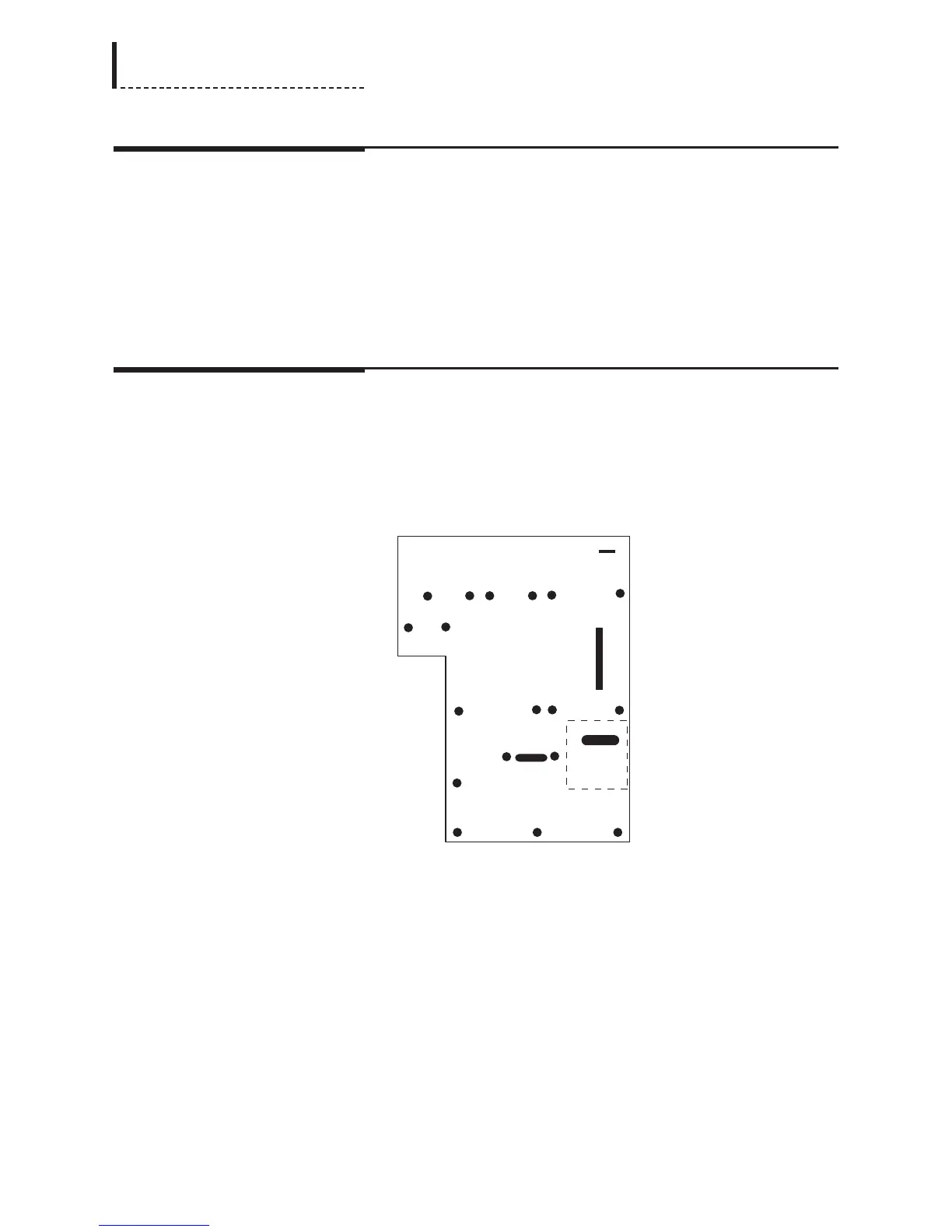
1. There are four screws that must be removed from the main board of the unit, and
replaced with the four supplied standoffs (part number 762-575). [Note: these
standoffs may be pre-installed on the main board of your unit.] These screws are
designated with * in the following diagram:
DPS-475/575
Main Board
The dashed rectangle indicates the position into which the DV I/O Option board
will be installed.
2. Replace the indicated screws with the standoffs.
3. Remove the DV I/O Option board from its protective bag.
4. Connect one end of the supplied cable (part number 774-140) to the NHE1
connector on the main board (see the above diagram for the location of this
connector). Connect the other end of the cable to connector CN603 on the DV
I/O Option board. The connectors are keyed, so the cable can only fit in the
correct orientation.
5. Inspect the connectors on the DV I/O Option and main board to ensure that all
pins are straight. Align the CN605 connector on the bottom of the DV I/O Option
196
DPS-475/575 Service Manual