Main Board
2. Remove the Animated Logo Option board from its protective bag.
3. Inspect the connectors on the Animated Logo Option and main board to ensure
that all pins are straight. Align the ACN1 connector on the bottom of the
Animated Logo Option board with connector RCN1 on the main board (see the
previous diagram of the main board, and the following diagram of the Animated
Logo Option board, for positioning). Gently press the Animated Logo Option
board onto the connector. Be sure to apply pressure evenly across the connector
to prevent the pins from bending or
breaking.
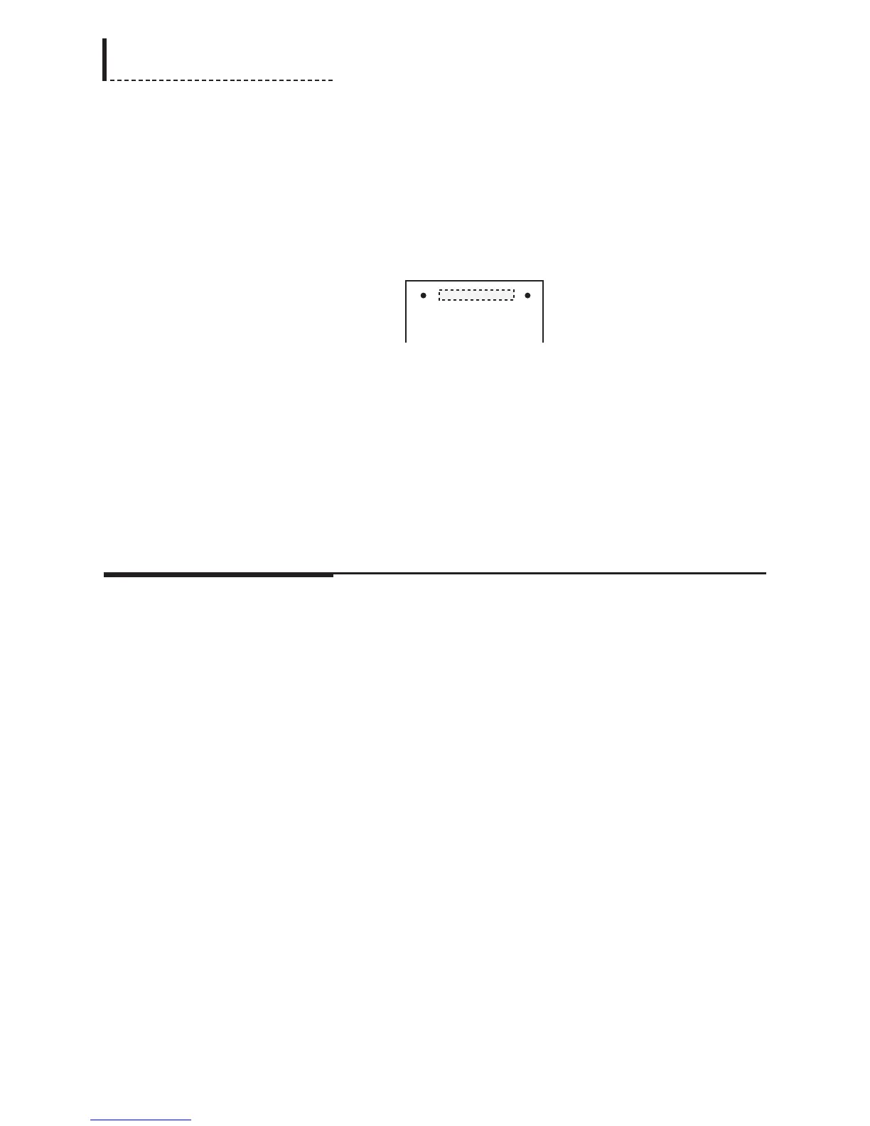
Animated Logo Option Board (Top View)
The dashed lines in the above diagram of the Animated Logo Option board
indicate the position of the connector on the bottom of the board.
4. Use the supplied screws (part number 751-010) to secure the Animated Logo
Option board to the standoffs in the main board.
Completing the Installation
1. Replace the top cover, and use the original fourteen screws to secure the top
cover.
2. Plug the power cord back in.
200
DPS-475/575 Service Manual