2. Replace the indicated screws with the standoffs.
3. On the rear of the unit, there is a cover plate where the AES/EBU DB25
connector will go. Remove the two screws holding this plate in place, and
remove the plate.
4. Remove the included aluminum shield and the Audio Synchronizer Module from
their protective bag.
5. Place the aluminum shield onto the standoffs. Line up the holes in the shield as
closely as possible with the standoffs.
6. If the terminal blocks for analog audio (part number 722-184) are plugged into
their mounting connectors on the Audio Synchronizer Module, remove them.
7. Align the DB25 connector on the Audio Synchronizer Module with the cutout for
it on the rear of the unit.
8. Inspect the connectors on the Audio Synchronizer Module and main board to
ensure that all pins are straight. With the shield sitting on the standoffs, gently
press connector J1 on the Audio Synchronizer Module onto the UHE1 connector
on the main board (see the previous diagram of the main board, and the
following diagram of the audio board, for positioning). Be sure to apply pressure
evenly across the connector to prevent the pins from bending or breaking.
IMPORTANT: It is imperative that all pins of the
connectors on both the main board and the Audio board
are lined up properly, both side-to-side and front-to-
back. If the connectors are not properly aligned, damage
will occur to the Module when the unit is powered up.
When properly aligned front-to-back, the analog audio
terminal block mounting connectors will be flush
with the rear of the chassis. This does NOT guarantee
proper pin alignment, however; alignment MUST be
checked visually prior to powering up the unit.
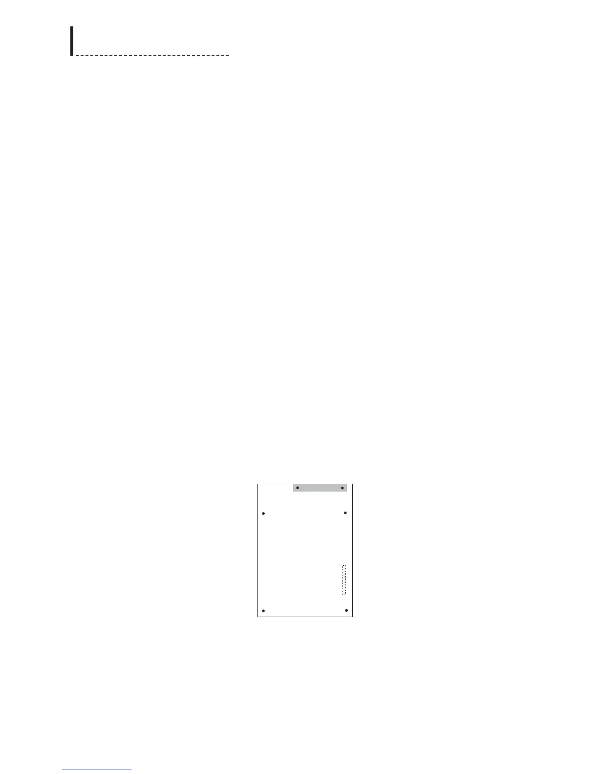
Audio Synchronizer Module (Top View)
The dashed lines in the previous diagram of the Audio Synchronizer Module
indicate the position of the connectors on the bottom of the board.
9. Use the supplied screws (part number 751-057) to secure the Audio Synchronizer
Module and the metal shield to the standoffs in the main board.
198
DPS-475/575 Service Manual