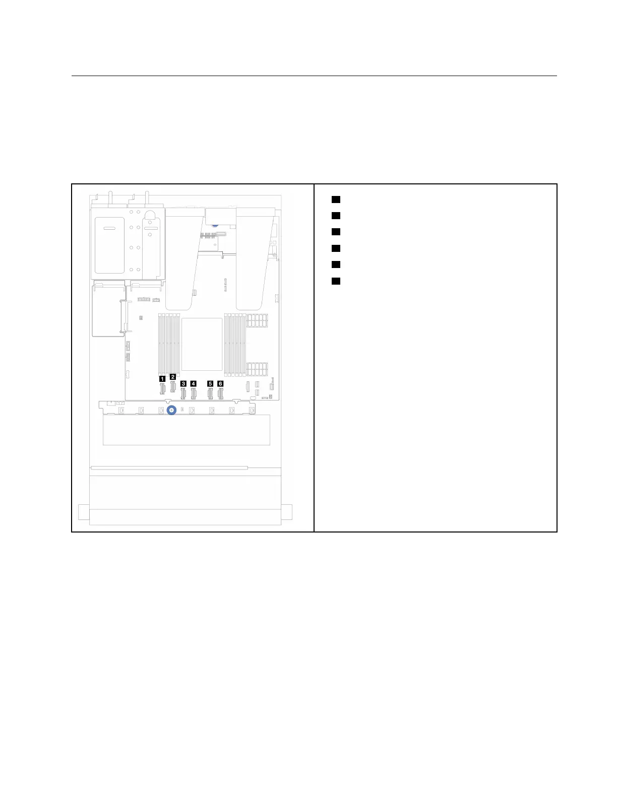
2.5-inch drive backplane (signal)
Use the section to understand the cable routing for signal cable connections for 2.5-inch drive backplanes.
Notes: For the server with a performance heat sink (T-shape), remove the heat sink before disconnecting or
connecting the cables which connect to PCIe 1, PCIe 2, PCIe 3, PCIe 4, PCIe 5, or PCIe 6 connectors (see
the table below). After disconnecting or connecting the cables, install the heat sink back to the server. See
“Remove a heat sink” on page 148 and “Install a heat sink” on page 151.
• 1 PCIe 1 Connector
•
2 PCIe 2 Connector
•
3 PCIe 3 Connector
•
4 PCIe 4 Connector
•
5 PCIe 5 Connector
•
6 PCIe 6 Connector
Your server supports the following server models with:
•
“10 x 2.5 AnyBay backplane” on page 262
4 x 2.5'' front drives
Use the section to understand the cable routing for signal cable connections for 4 x 2.5'' front drive
backplanes.
4 x 2.5'' SAS/SATA backplane
Use this section to understand the SAS/SATA backplane cable routing for server model with four 2.5-inch
front drives.
• For the locations of connectors on the processor board, refer to “System-board-assembly connectors” on
page 33
.
Chapter 6. Internal cable routing 247

 Loading...


