Step 1. Touch the static-protective package that contains the backplane to any unpainted surface on the
outside of the server. And then, take the backplane out of the package and place it on a static-
protective surface.
Step 2. Connect the cables to the backplane. See
Chapter 6 “Internal cable routing” on page 217.
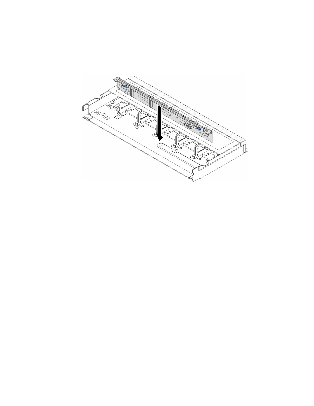
Step 3. Align the two pins on the backplane with the corresponding holes in the chassis.
Figure 21. Installation of backplane for ten 2.5-inch hot-swap drives
Step 4. Lower the backplane into the chassis. Ensure that the pins pass through the holes and the
backplane is fully seated in place.
Step 5. Connect the cables to the system board or expansion slots. See
Chapter 6 “Internal cable routing”
on page 217
.
After you finish
1. Reinstall all the drives and drive fillers into the drive bays. See
“Install a 2.5-inch hot-swap drive” on
page 100
.
2. Complete the parts replacement. See
“Complete the parts replacement” on page 215.
Remove the front 16-EDSFF drive backplane
Use this information to remove the backplane for front 16 EDSFF drives.
About this task
Attention:
• Read “Installation Guidelines” on page 45 and “Safety inspection checklist” on page 46 to ensure that you
work safely.
• Power off the server and disconnect all power cords for this task.
• Prevent exposure to static electricity, which might lead to system halt and loss of data, by keeping static-
sensitive components in their static-protective packages until installation, and handling these devices with
an electrostatic-discharge wrist strap or other grounding system.
Watch the procedure
62
ThinkSystem SR635 V3 User Guide

 Loading...


