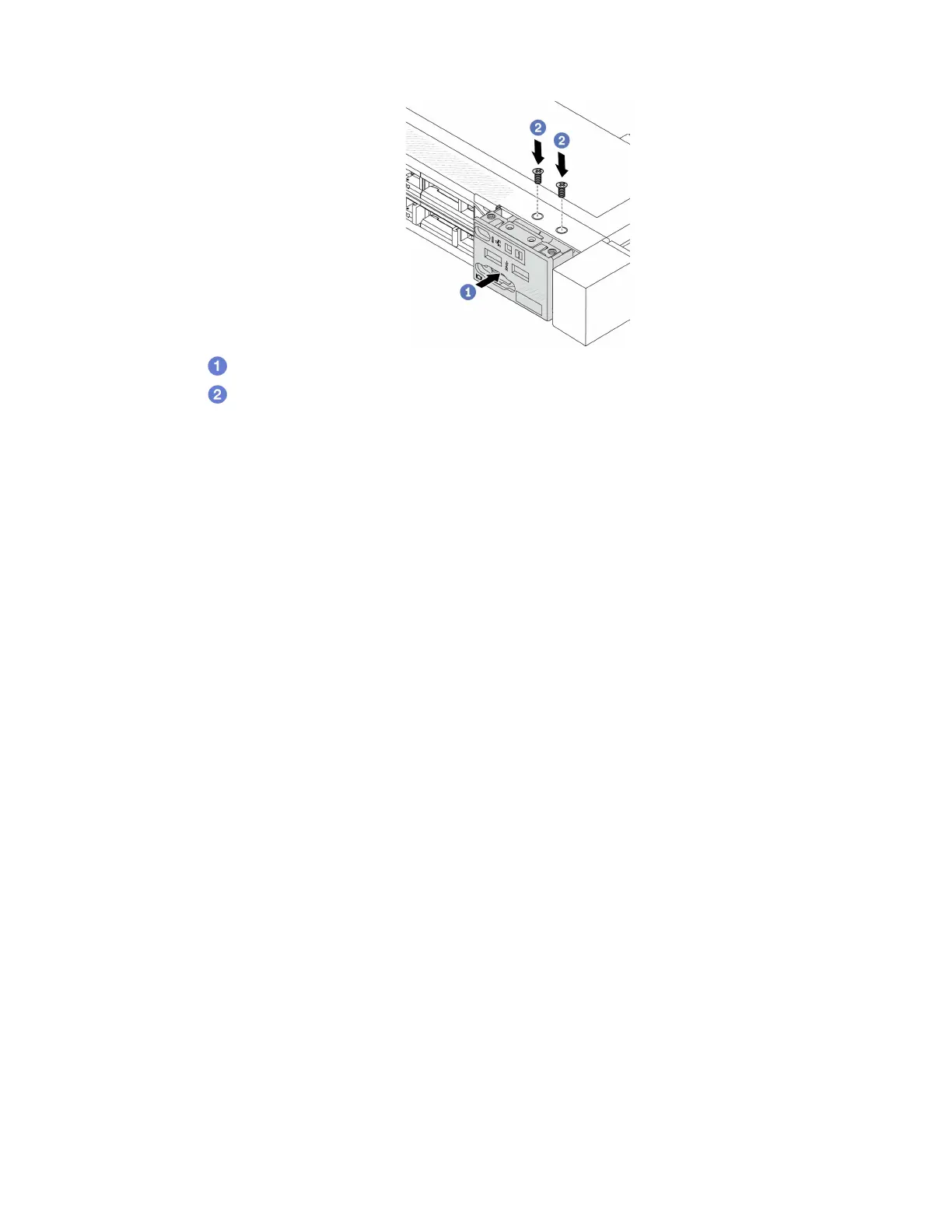
a. Insert the front I/O module into the front chassis.
b.
Install the screws to secure the front I/O module in place.
After you finish
1. Connect the front I/O cables to the system board. See
“Front I/O module cable routing” on page 224.
2. Complete the parts replacement. See
“Complete the parts replacement” on page 215.
Remove the Integrated Diagnostics Panel assembly
Use this information to remove the Integrated Diagnostics Panel assembly.
About this task
Attention:
• Read
“Installation Guidelines” on page 45 and “Safety inspection checklist” on page 46 to ensure that you
work safely.
• Power off the server and disconnect all power cords for this task.
• Prevent exposure to static electricity, which might lead to system halt and loss of data, by keeping static-
sensitive components in their static-protective packages until installation, and handling these devices with
an electrostatic-discharge wrist strap or other grounding system.
Watch the procedure
A video of this procedure is available at YouTube:
https://www.youtube.com/playlist?list=PLYV5R7hVcs-
DrpxDWLMfgtXO4O6BVYTim
.
Procedure
Step 1. Remove the top cover. See
“Remove the top cover” on page 212.
Step 2. If the security bezel is installed, remove it. See
“Remove the security bezel” on page 183.
Chapter 5. Hardware replacement procedures 81

 Loading...


