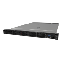
The following illustration shows the layout of the system board assembly which contains the firmware and
RoT security module, system I/O board, processor board, fan board and PIB board.
Figure 13. System-board-assembly layout
1 System I/O board
2 Firmware and RoT security module
3 Processor board 4 Fan board
5 PIB board
•
“System-board-assembly connectors” on page 33
• “System-board-assembly switches” on page 34
• “System-board-assembly LEDs” on page 297
32
ThinkSystem SR635 V3 User Guide

 Loading...


