Watch the procedure
A video of this procedure is available at YouTube:
https://www.youtube.com/playlist?list=PLYV5R7hVcs-
DrpxDWLMfgtXO4O6BVYTim
.
Procedure
Step 1. Remove the top cover. See “Remove the top cover” on page 212.
Step 2. If the security bezel is installed, remove it. See
“Remove the security bezel” on page 183.
Step 3. Disconnect the front I/O cables from the system board. See
“Front I/O module cable routing” on
page 224
.
Notes:
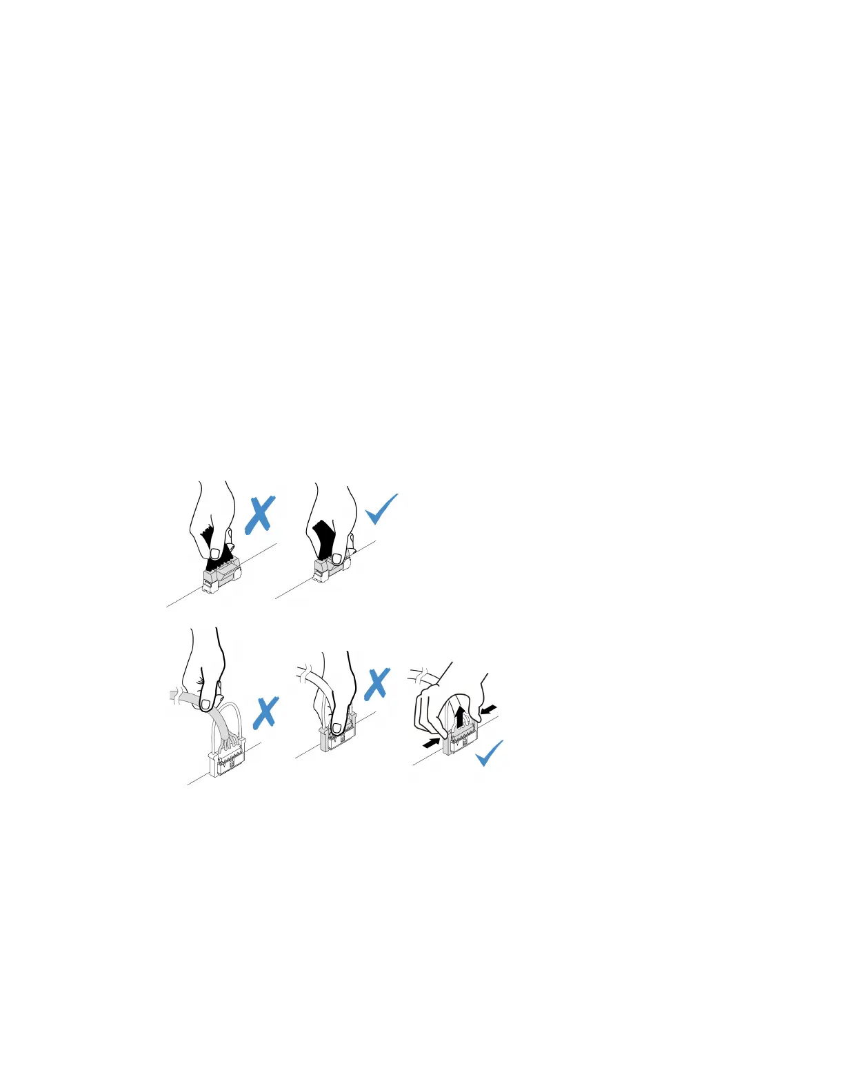
• If you need to disconnect cables from the system board assembly, disengage all latches or
release tabs on cable connectors first. Failing to release the tab before removing the cables will
damage the cable sockets on the system board assembly. Any damage to the cable sockets
might require replacing the system board assembly.
• The connectors on your system board assembly might look different from those in the
illustration, but the removal procedure is the same.
1. Press the release tab to release the connector.
2. Disengage the connector from the cable socket.
Figure 37. Disconnecting cables from the system board assembly
Chapter 5. Hardware replacement procedures 79

 Loading...


