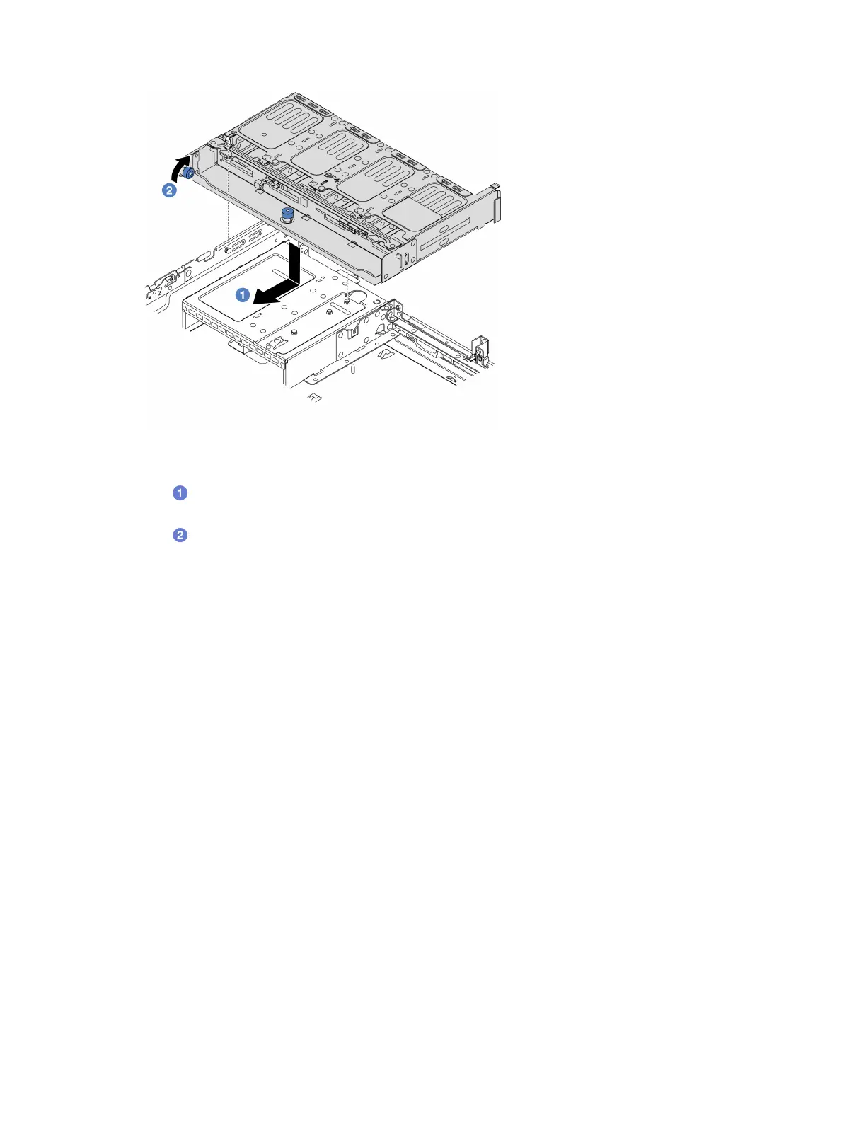
Figure 200. Installing the 8 x 2.5-inch rear drive cage
a. Align the rear drive cage with the chassis, and lower the drive cage into the chassis. Move
the rear drive cage forward until it clicks into position.
b.
Twist and release the blue plunger to secure the drive cage in place.
Step 5. Connect cables from the drive backplanes to the system board or RAID/HBA adapters. See
Chapter 6 “Internal cable routing” on page 271.
After you finish
1. Reinstall the drives or drive fillers into the rear drive cage. See “Install a hot-swap drive” on page 83.
2. Complete the parts replacement. See
“Complete the parts replacement” on page 269.
Remove the 2 x 3.5" drive backplane and drive cage
Use this information to remove the rear 3.5-inch 2-bay drive backplane and drive cage.
About this task
Attention:
• Read
“Installation Guidelines” on page 55 and “Safety inspection checklist” on page 56 to ensure that you
work safely.
• Power off the server and peripheral devices and disconnect the power cords and all external cables. See
“Power off the server” on page 73.
• Prevent exposure to static electricity, which might lead to system halt and loss of data, by keeping static-
sensitive components in their static-protective packages until installation, and handling these devices with
an electrostatic-discharge wrist strap or other grounding system.
• Before you remove or make changes to drives, drive controllers (including controllers that are integrated
on the system board assembly), drive backplanes or drive cables, back up all important data that is stored
on drives.
228
ThinkSystem SR650 V3 User Guide

 Loading...


