Table 19. Component identification (Top view) (continued)
5 Processor and heat sink modules (PHM)
6 Riser assemblies
note 1
7 System board assembly 8 CFF RAID adapter/expander
note 2
Notes:
1. The illustration shows the server rear configuration with three riser assemblies. The server rear
configurations vary by server model. For details, see
“Rear view” on page 24.
2. The illustration shows the server with CFF adapters which are available only in the 2.5-inch chassis. In
some configurations, there might be installed with a RAID flash power module. For details, see
Table 32
“Location of RAID flash power modules” on page 198
.
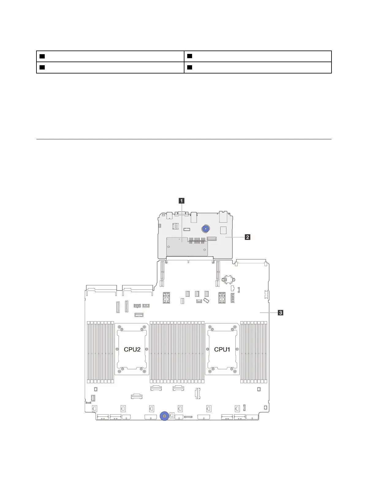
System-board-assembly layout
This section provides information about the connectors, switches, and jumpers that are available on the
system board assembly.
The following illustration shows the layout of the system board assembly which contains the firmware and
RoT security module, system I/O board, and processor board.
Figure 12. System-board-assembly layout
34 ThinkSystem SR650 V3 User Guide

 Loading...


