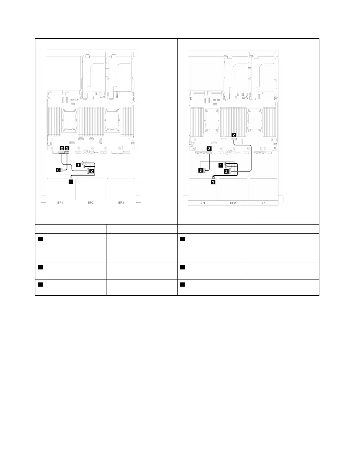
Figure 281. Cable routing when two processors installed
Figure 282. Cable routing when one processor installed
From To From To
1 Backplane 1: SAS CFF adapter
• C0
• C1
1 Backplane 1: SAS CFF adapter
• C0
• C1
2 CFF adapter: MB (CFF
input)
Onboard: PCIe 7 2 CFF adapter: MB (CFF
input)
Onboard: PCIe 4
3 CFF adapter: PWR Onboard: CFF RAID/HBA
PWR
3 CFF adapter: PWR Onboard: CFF RAID/HBA
PWR
One 8 x AnyBay backplane (Gen 4)
This section provides cable routing information for the server model with one 8 x 2.5-inch AnyBay front drive
backplane (Gen 4).
To connect power cables for the front backplane(s), refer to
“Backplanes: server models with 2.5-inch front
drive bays” on page 297
.
To connect signal cables for the front backplane(s), refer to the following cable routing scenarios depending
on your server configuration.
•
“8i/16i RAID/HBA adapter” on page 302
• “CFF 8i/16i RAID/HBA adapter” on page 304
8i/16i RAID/HBA adapter
The following shows the cable connections for the 8 x 2.5-inch AnyBay (Gen 4) configuration with one 8i/16i
RAID/HBA adapter.
302
ThinkSystem SR650 V3 User Guide

 Loading...


