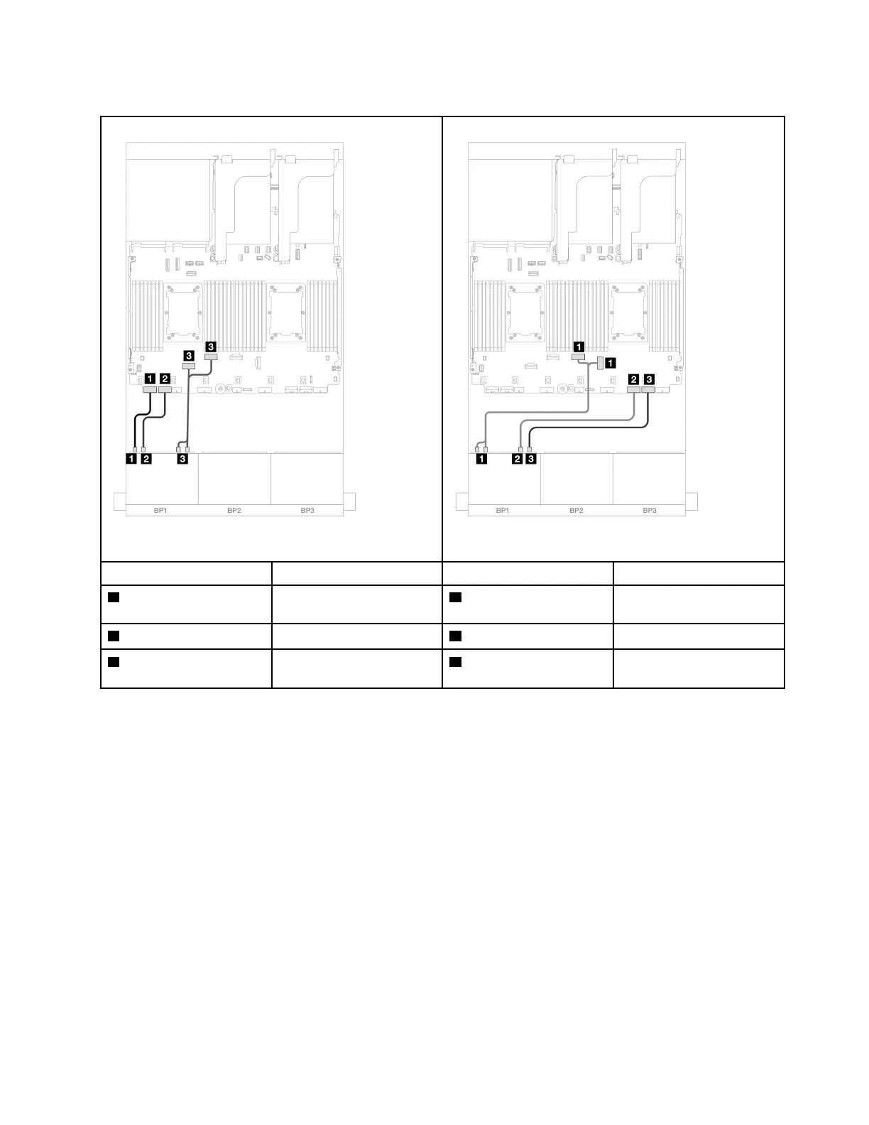
NVMe cable routing to onboard PCIe connectors
Figure 288. Cable routing when two processors installed Figure 289. Cable routing when one processor installed
From To From To
1 Backplane 1: NVMe 0-1
Onboard: PCIe 8
1 Backplane 1: NVMe 0-1,
2-3
Onboard: PCIe 3, 4
2 Backplane 1: NVMe 2-3 Onboard: PCIe 7 2 Backplane 1: NVMe 4-5 Onboard: PCIe 2
3 Backplane 1: NVMe 4-5,
6-7
Onboard: PCIe 6, 5
3 Backplane 1: NVMe 6-7 Onboard: PCIe 1
Two 8 x SAS/SATA backplanes
This section provides cable routing information for the server model with two 8 x 2.5-inch SAS/SATA front
drive backplanes.
To connect power cables for the front backplane(s), refer to
“Backplanes: server models with 2.5-inch front
drive bays” on page 297
.
To connect signal cables for the front backplane(s), refer to the following cable routing scenarios depending
on your server configuration.
• “16 x SAS/SATA” on page 308
– “Onboard connectors + 8i RAID/HBA adapter” on page 308
– “8i/16i RAID/HBA adapter” on page 309
– “CFF 16i RAID/HBA adapter” on page 310
• “14 x SAS/SATA” on page 310
Chapter 6. Internal cable routing 307

 Loading...


