Ensure that the front panel cover fixing bolts have been tightened to 4Nm torque to maintain
the integrity of the IP69K rating for the head; preventing ingress of water or condensation.
European Colour North America Colour Terminal
LIVE Brown or Black HOT Black L
NEUTRAL Blue NEUTRAL White N
EARTH Green/Yellow GROUND Green E
SCREEN - SCREEN - E
Do not use rigid conduit of any type. Rigid conduit can lead to vibration being transmitted to
other components, resulting in spurious triggering / rejects.
Disconnecting the Power
Before disconnecting the detector head from its power source, ensure that any signal cables
connected to other equipment are disconnected first.
Input / Output Signal Information
To connect to external devices a Relay kit, Loma part number 6120PL500, consisting of a relay
module, a cable that connects the relay module to the mini control board and some cable ties, can be
supplied.
Please refer to Loma Drawing 5000/C3/69405 – IQ
3
+ Miniboard External Relays Block Diagram. A
copy of the diagram is supplied with the detector head and can also be obtained by contacting your
local Loma Service Centre.
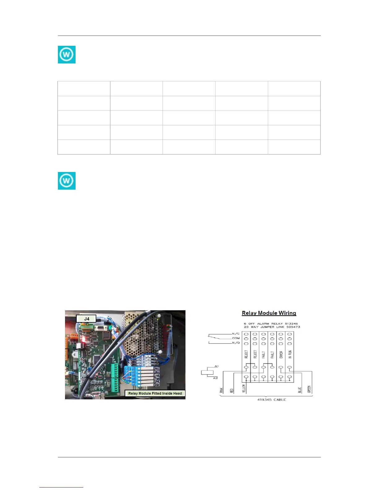
You can fit the relay module into the head using the supplied connecting cable as shown in the picture
below or alternatively you can also fit the Relay module into an external electrical box. This will
require a longer connecting cable (2.6 m) which is available from Loma under part number 419343.
To power external sensors and PECs, jumper JP7 on the mini control board is used to set the output
voltage provided by the mini control board to either 12V or 24V as required.
When the jumper is set to the VEXT position, 24V is provided on TBA2 – Pin 6.
When the jumper is set to the +12V (VP) position, 12V is provided on TBA1 – Pin 6.