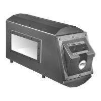
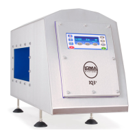
Installation
44
■ Raise the forks sufficiently to lift the machine clear of the ground and any obstacles.
■
Carefully move the machine to the required location.
■
Lower the forks and withdraw them from the machine.
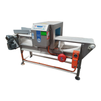
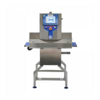
Adjusting / Levelling the Conveyor
For systems supplied that incorporate one or a number of conveyors the operating height may need
to be adjusted so that it can be integrated into your production line.
■
Adjust the infeed and outfeed heights as necessary by means of either the adjustable feet or
adjustable wheels. Then lock the wheels (if fitted).
■
Ensure that all feet or wheels are firmly on the ground, and are evenly supporting the conveyor
so that it does not rock.
■
If necessary, anchor the conveyor to the ground using bolts screwed into the feet.
■
Do not fasten the conveyor to any other piece of machinery as this could lead to vibration being
transmitted to other parts of the machine, resulting in spurious triggering / rejects.
■
If the conveyor is fitted with feet, you are recommended to apply silicone sealant around the
feet and floor.
Clearance Requirements
From safety and operational viewpoints, it is important that sufficient free space is left around the
machine, specifically the front and back, to enable commissioning and for maintenance personnel to
easily gain access to components.
It is recommended that wherever possible a minimum of 1 metre free space is available at the front of
the machine and 1 metre at the rear.
Connecting the Air Supply
Do not start the machine and initiate the use of any compressed air before the Loma
commissioning engineer has approved the installation.
Except where a metal detector head only is being supplied, all Loma metal detector systems require a
clean and dry compressed air supply, primarily to operate the optional automatic reject system.
It is therefore essential that the air supply is robust enough for correct operation of the system when
the reject operates.
■
Pneumatic Assembly – The pneumatic system consists of the following components:
o
Isolator Switch – The external air supply is connected to the switch which is used to turn
the supply to the system on and off. The air supply is then fed into the Air Regulator.
operation whilst carrying out servicing and maintenance activities.
o Air Regulator – The air regulator is used to set the air pressure being supplied to the
system. A drain trap is provided to remove any water that collects in the system. See the
Maintenance section for further details. The air supply is then fed into the Dump Valve.
o Dump Valve – The dump valve is a safety device that dumps air pressure from the system
in an emergency to protect the operator. It also includes a soft start feature which allows
air pressure to build slowly following an air pressure dump to prevent damage or injury.
The air supply is fed from the valve to the input connection on the Reject Valve.