EasyManuals Logo

LSIS G100 User Manual

LSIS G100
343 pages
To Next Page IconTo Next Page
To Previous Page IconTo Previous Page
Page #198 background imageLoading...
Page #198 background image
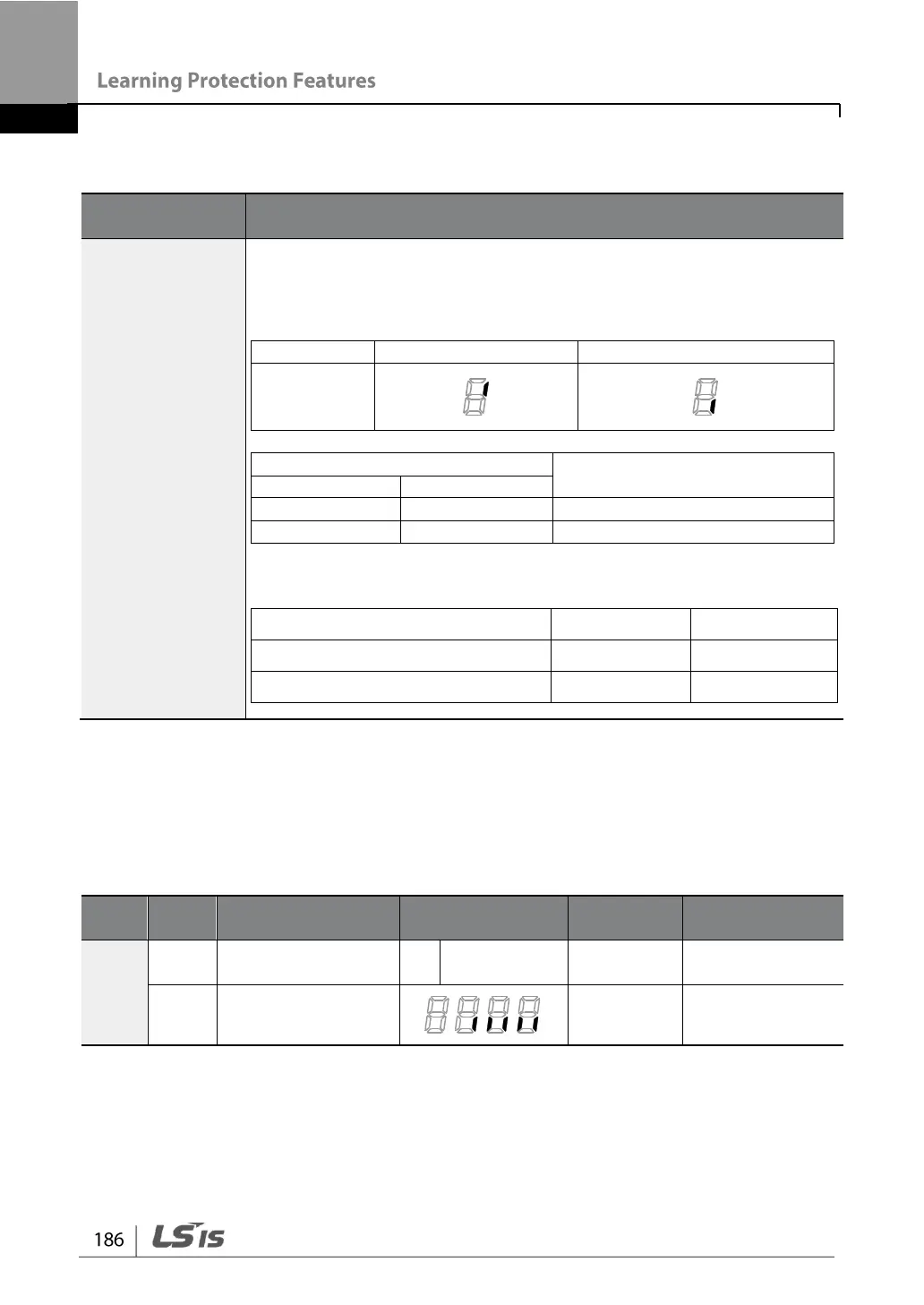
Input and Output Open-phase Protection Setting Details
Code and
Features
Description
Pr.05 Phase Loss
Chk,
Pr.06 IPO V Band
Input and output phase protection can each be selected. When the dot
is displayed above the switch, the corresponding bit is set to on. When
it is below the switch, it is set to on.
Items
Bit On Status
Bit Off Status
Keypad
Configuration
Function
bit2
bit1
Output open-phase protection
Input open-phase protection
Initial values by each product on input voltage range during open-
phase are shown as below.
Items
Initial Value
Unit
0.4 kW2.2 kW (200 V/400 V)
15
V
4.0 kW7.5 kW (200 V/400 V)
13
V
6.2.2 External Trip Signal
Set one of the multi-function input terminals to 4 (External Trip) to allow the inverter to
stop operation by using external signals.
Grou
p
Code
Name
Setting
Setting
Range
Unit
In
6569
Px terminal setting
options
4
External Trip
-
-
87
Multi-function input
terminal selection
-
bit

Table of Contents

Other manuals for LSIS G100

Questions and Answers:

Question and Answer IconNeed help?

Do you have a question about the LSIS G100 and is the answer not in the manual?

LSIS G100 Specifications

General IconGeneral
BrandLSIS
ModelG100
CategoryInverter Drive
LanguageEnglish

Related product manuals