EasyManuals Logo

LSIS G100 User Manual

LSIS G100
343 pages
To Next Page IconTo Next Page
To Previous Page IconTo Previous Page
Page #99 background imageLoading...
Page #99 background image
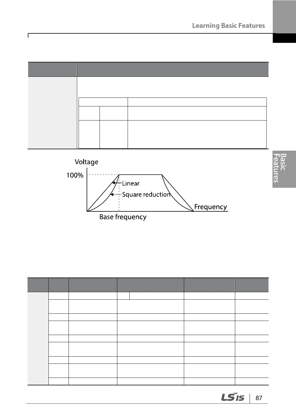
Square Reduction V/F Pattern Operation - Setting Details
Code and
Features
Description
bA.07 V/F
Pattern
Sets the parameter value to 1 (Square) or 2 (Square2) according to
the load’s start characteristics.
Configuration
Function
1
Square
The inverter produces output voltage proportional
to 1.5 square of the operation frequency.
3
Square
2
The inverter produces output voltage proportional
to 2 square of the operation frequency. This
setup is ideal for variable torque loads such as
fans or pumps.
4.11.3 User V/F Pattern Operation
The inverter allows the configuration of user-defined V/F patterns to suit the load
characteristics of special motors.
Grou
p
Code
Name
Setting
Setting Range
Unit
bA
07
V/F pattern
2
User V/F
03
-
41
User Frequency
1
15.00
0Max
Frequency
Hz
42
User Voltage 1
25
0100
%
43
User Frequency
2
30.00
0Max
Frequency
Hz
44
User Voltage 2
50
0100
%
45
User Frequency
3
45.00
0Max
Frequency
Hz
46
User Voltage 3
75
0100
%
47
User Frequency
4
Maximum frequency
0Max
Frequency
Hz
48
User Voltage 4
100
0100%
%

Table of Contents

Other manuals for LSIS G100

Questions and Answers:

Question and Answer IconNeed help?

Do you have a question about the LSIS G100 and is the answer not in the manual?

LSIS G100 Specifications

General IconGeneral
BrandLSIS
ModelG100
CategoryInverter Drive
LanguageEnglish

Related product manuals