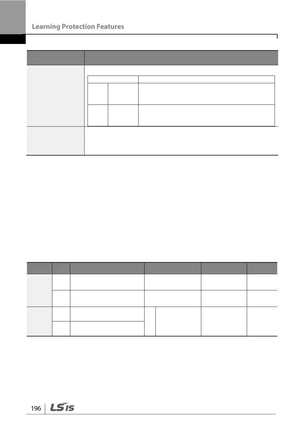
Set the cooling fan fault mode.
The inverter output is blocked and the fan trip
is displayed when a cooling fan error is
detected.
When OU.33 (Relay 2) and OU.31 (Relay 1)
are set to 8 (FAN Warning), the fan error signal
is output and the operation continues.
When the code value is set to 8 (FAN Warning), the fan error signal
is output and operation continues. However, when the inverter inside
temperature rises above a certain level, output is blocked due to
activation of overheat protection.
6.3.2 Lifetime Diagnosis of Components
Lifetime Diagnosis for Fans
Enter the Pr-87 (Fan exchange warning level) code (%). After the selected usage (%)
is reached (out of 50,000 hours), the fan exchange warning message will appear in
the multi-functional output or keypad.
The total fan usage level (%) appears at Pr-86. When exchanging fans, you may
initialize the accumulated value to 0 by setting the Pr-88 (Initializing accumulated time
for cooling fans) to 1.
Accumulated percent of
fan usage
Fan exchange warning
Level
Multi-function relay 1
item
Multi-function relay 2
item
6.3.3 Low Voltage Fault Trip
When inverter input power is lost and the internal DC link voltage drops below a
certain voltage level, the inverter stops output and a low voltage trip occurs.