EasyManuals Logo

LSIS G100 User Manual

LSIS G100
343 pages
To Next Page IconTo Next Page
To Previous Page IconTo Previous Page
Page #22 background imageLoading...
Page #22 background image
1.5 Cable Selection
When you install power and signal cables in the terminal blocks, only use cables that
meet the required specification for the safe and reliable operation of the product.
Refer to the following information to assist you with cable selection.
Wherever possible use cables with the largest cross-sectional area for mains power
wiring, to ensure that voltage drop does not exceed 2%.
Use copper cables rated for 600 V, 75 for power terminal wiring.
Use copper cables rated for 300 V, 75 for control terminal wiring.
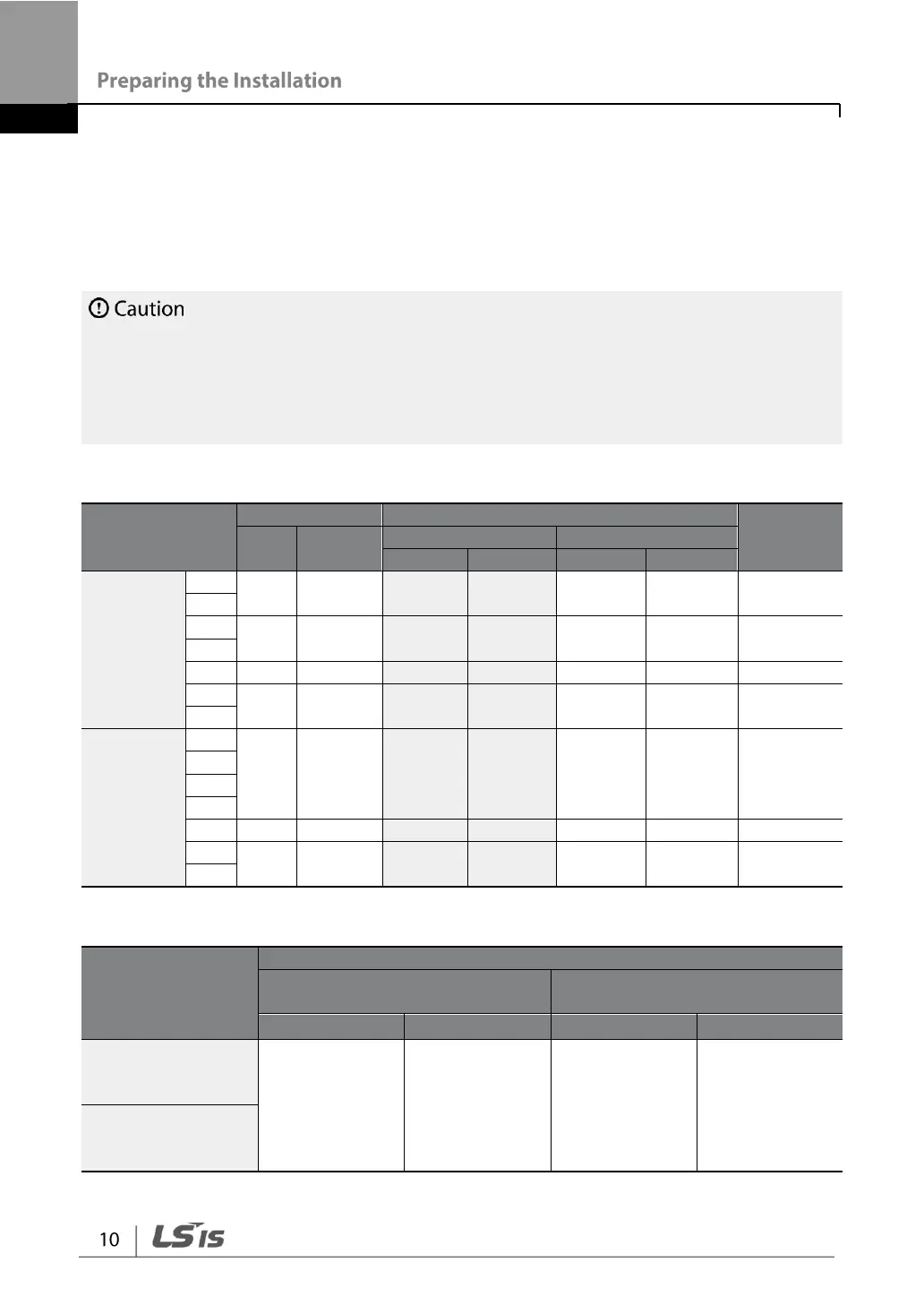
Ground Cable and Power Cable Specification
Capacity (kW)
Ground
Power Terminal Wiring
Terminal
Block Size
mm
2
AWG
mm
2
AWG
R/S/T
U/V/W
R/S/T
U/V/W
3Phase
200 V
0.4
4
12
1.5
1.5
16
16
M3
0.75
1.5
4
12
4
2.5
12
14
M4
2.2
4
6
10
6
6
10
10
M4
5.5
6
10
16
10
6
8
M4
7.5
3Phase
400 V
0.4
2.5
14
1.5
1.5
16
16
M3.5
0.75
1.5
2.2
4
6
10
2.5
2.5
14
14
M4
5.5
6
10
10
6
8
10
M4
7.5
Signal (Control) Cable Specifications
Terminals
Control Terminal Wiring
Without Crimp Terminal
Connectors
With Crimp Terminal
Connectors
mm
2
AWG
mm
2
AWG
24/P1,
P2P5,
CM
0.8
18
0.5
20
A1/B1/C1/A2/C2,
VR/V1/I2/AO/CM,
S+/S-

Table of Contents

Other manuals for LSIS G100

Questions and Answers:

Question and Answer IconNeed help?

Do you have a question about the LSIS G100 and is the answer not in the manual?

LSIS G100 Specifications

General IconGeneral
BrandLSIS
ModelG100
CategoryInverter Drive
LanguageEnglish

Related product manuals