EasyManuals Logo

LSIS G100 User Manual

LSIS G100
343 pages
To Next Page IconTo Next Page
To Previous Page IconTo Previous Page
Page #35 background imageLoading...
Page #35 background image
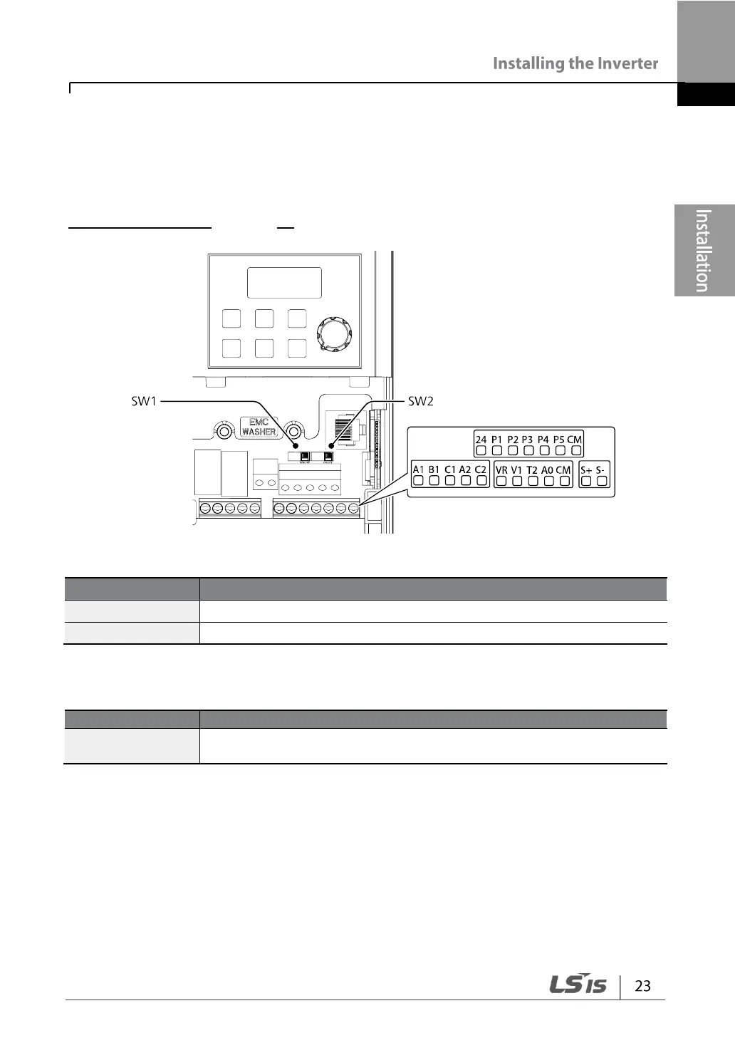
Step 4 Control Terminal Wiring
The illustrations below show the detailed layout of control wiring terminals, and control
board switches. Ensure that the cables selected meet or exceed the specifications in
1.5 Cable Selection on page 10 before installing them.
Control Board Switches
Switch
Description
SW1
NPN/PNP mode selection switch
SW2
Terminating Resistor selection switch
Connector
Name
Description
RJ-45 Connector
Connect to Remote I/O or smart copier, connect with RS-485
communication.

Table of Contents

Other manuals for LSIS G100

Questions and Answers:

Question and Answer IconNeed help?

Do you have a question about the LSIS G100 and is the answer not in the manual?

LSIS G100 Specifications

General IconGeneral
BrandLSIS
ModelG100
CategoryInverter Drive
LanguageEnglish

Related product manuals