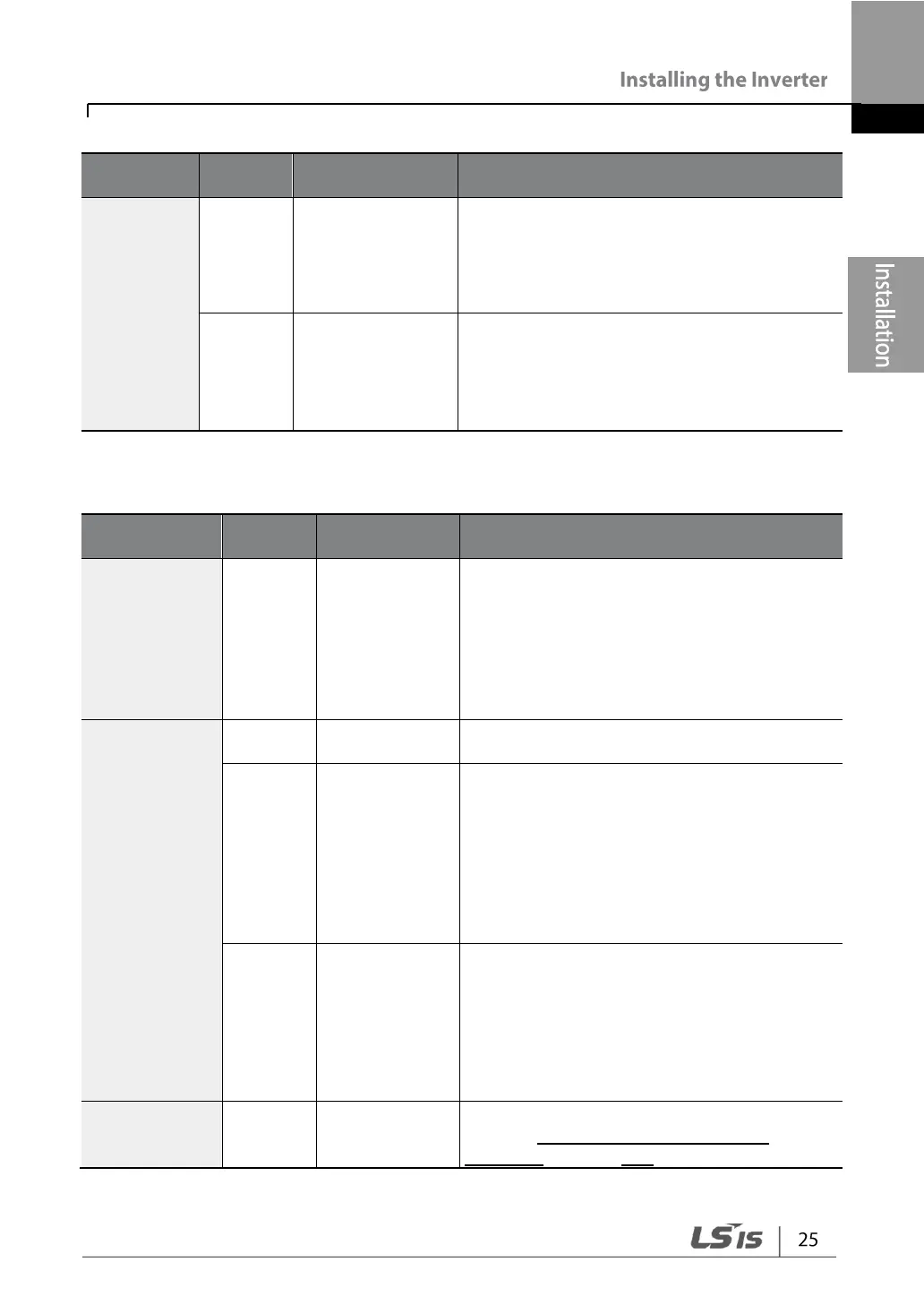
Frequency setting
(voltage) terminal
Used to setup or modify the frequency
depending on the voltage input to the V1
terminal.
• Unipolar: 0–10 V (12 V Max.)
• Bipolar: -10–10 V (±12 V Max.)
Current input for
frequency
reference input
Terminal
Used to setup or modify a frequency
reference via the I2 terminal.
• Input current: 4–20 mA
• Maximum Input current: 20 mA
• Input resistance: 249 Ω
Output/Communication Terminal Labels and Descriptions
Used to send inverter output information to
external devices: output frequency, output
current, output voltage, or a DC voltage.
• Output Voltage: 0–10 V
• Maximum output voltage/current: 12 V, 10
mA
• Factory default output: Frequency
External 24V
power source
Maximum Current Output: 100 mA
Sends out alarm signals when the inverter’s
safety features are activated (AC 250 V <1
A, DC 30 V < 1 A).
• Fault condition: A1 and C1 contacts are
connected (B1 and C1 open connection)
• Normal operation: B1 and C1 contacts
are connected (A1 and C1 open
connection)
Sends out alarm signals when the inverter’s
safety features are activated (AC 250 V <1
A, DC 30 V < 1 A).
• Fault condition: A2 and C2 contacts are
open connection
• Normal operation: A2 and C2 contacts
are connected
RS-485 signal
input terminal
Used to send or receive RS-485 signals.
Refer to 7 RS-485 Communication
Features on page 208 for more details.