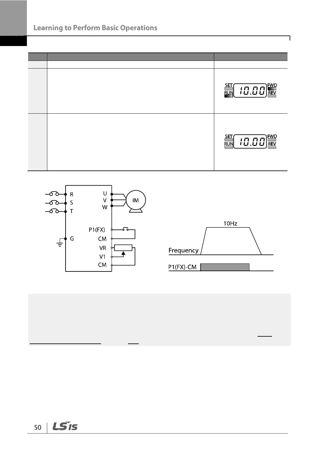
frequency reference to 10 Hz.
Refer to the wiring diagram at the bottom of the table,
and turn on the switch between the P1 (FX) and CM
terminals.
The RUN indicator light flashes and the FWD indicator
light comes on steady. The current acceleration
frequency is displayed.
When the frequency reference is reached (10 Hz), open
the switch between the P1 (FX) and CM terminals.
The RUN indicator light flashes again and the current
deceleration frequency is displayed.
When the frequency reaches 0 Hz, the RUN and FWD
indicator lights turn off, and the frequency reference,
10.00, is displayed again.
[Wiring Diagram] [Operation Pattern]
The instructions in the table are based on the factory default parameter settings. The
inverter may not work correctly if the default parameter settings are changed after the
inverter is purchased. In such cases, initialize all parameters to reset the values to factory
default parameter settings before following the instructions in the table (refer to 5.21
Parameter initialization on page 157).

 Loading...
