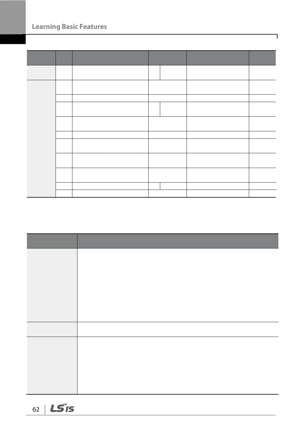
Frequency reference
source
Frequency for maximum
analog input
Start Frequency–
Max. Frequency
V1 input polarity selection
V1 input filter time
constant
V1 output at Minimum
voltage (%)
V1 output at Maximum
voltage (%)
Rotation direction options
* Quantizing is disabled if "0" is selected.
0–10 V Input Voltage Setting Details
Configures the frequency reference at the maximum input voltage when
a potentiometer is connected to the control terminal block. A frequency
set with code In.01 becomes the maximum frequency only if the value
set in code In.11 (or In.15) is 100.00%.
• Set code In.01 to 40.00 and use default values for codes In.02–
In.16. Motor will run at 40.00 Hz when a 10 V input is provided at V1.
• Set code In.11 to 50.00 and use default values for codes In.01–
In.16. Motor will run at 30.00 Hz (50% of the default maximum
frequency–60 Hz) when a 10 V input is provided at V1.
Configures the inverter to monitor the input voltage at V1.
As a low-pass filter, use if there is significant variation of frequency
parameter setting value due to high noise level. When used, it filters the
analog signal to pass only the clean input signals. The higher the
number of time constant filter, the lower the variation in frequency.
However this slows down the time t and thus affects the response time.
The value t (time) indicates the time required for the frequency to reach
63% of the reference, when external input voltages are provided in
multiple steps.