I2 output at minimum
current (%)
I2 output at Maximum
current (%)
Changing rotation direction
of I2
* Quantizing is disabled if "0" is selected.
Input Current (I2) Setting Details
Configures the frequency reference for operation at the maximum
current (when In.56 is set to 100%).
• If In.01 is set to 40.00, and default settings are used for In.53–56,
20 mA input current to the I2 terminal will produce a frequency
reference of 40.00 Hz.
• If In.56 is set to 50.00, and default settings are used for In.01 and
In.53–55, 20 mA input current (max) to I2 will produce a frequency
reference of 30.00 Hz.
Used to monitor input current at I2.
Configures the time for the operation frequency to reach 63% of target
frequency based on the input current at I2.
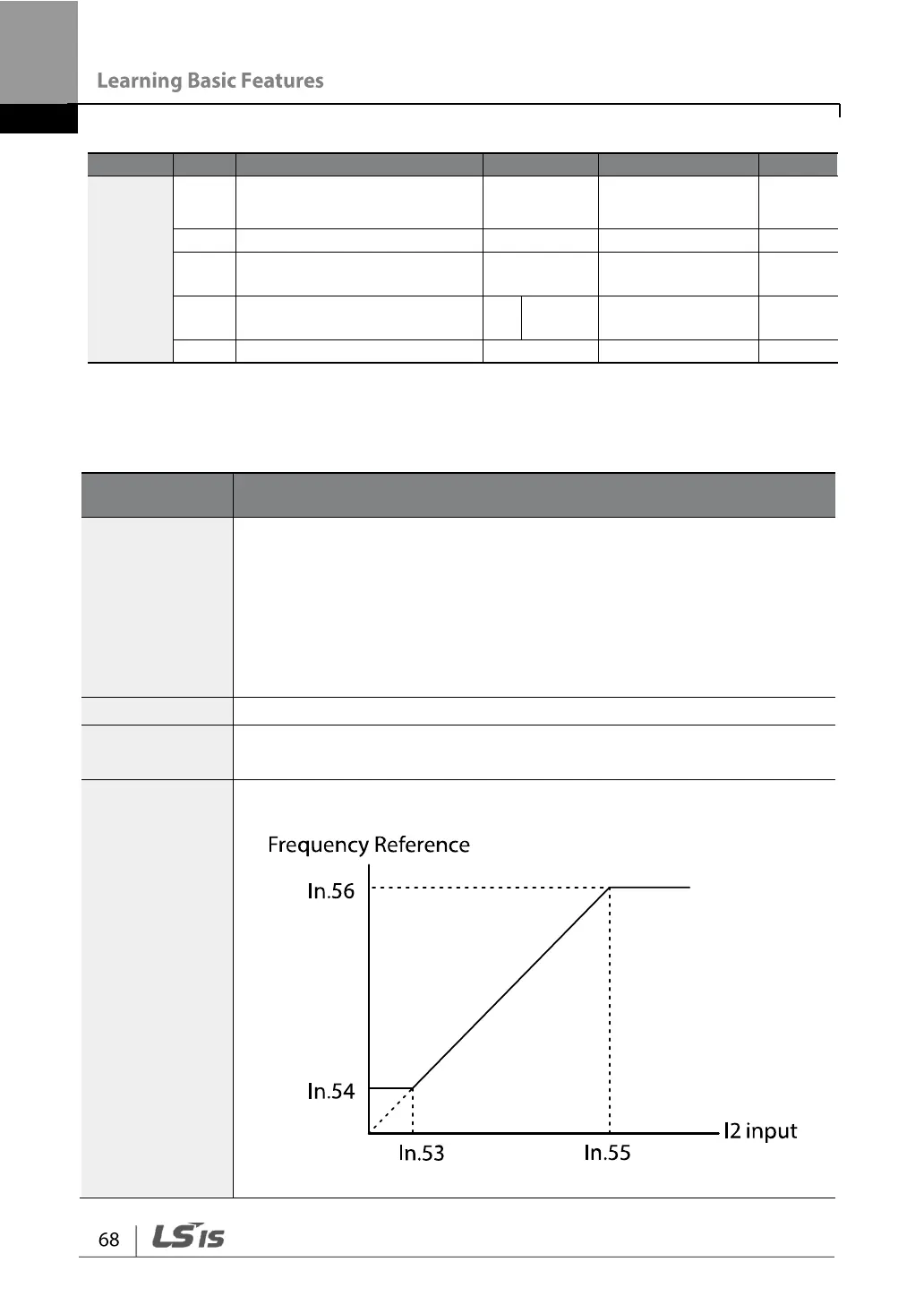
In.53 I2 Curr x1–
In.56 I2 Perc y2
Configures the gradient level and off-set value of the output frequency.