214713 103 Revision A
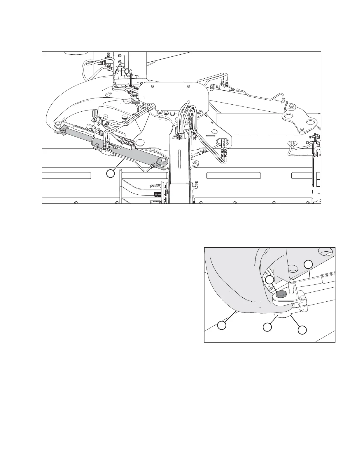
Figure 5.22: Hydraulic System
1022618
A
NOTE:
Ensure there is no contact with the rear link arm when the hitch swing cylinder extends.
2. With the cylinder disconnected from the rear arm link, using the tractor’s hydraulics, extend and retract swing
cylinder (A) several times to purge any air in the cylinder.
Figure 5.23: Rear Arm Link
3. Align the clevis pinholes in the cylinder clevis (B), cam
arm (C), and rear link arm (A). Install clevis pin (D) and
secure with cotter pin (E).
SETTING UP THE TRACTOR
 Loading...


