214713 213 Revision A
11.6.4 Flare-Type Hydraulic Fittings
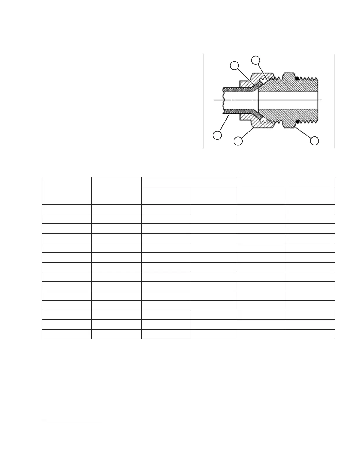
Figure 11.17: Hydraulic Fitting
1. Check flare (A) and flare seat (B) for defects that might
cause leakage.
2. Align tube (C) with fitting (D) and thread nut (E) onto
fitting without lubrication until contact has been made
between flared surfaces.
3. Torque fitting nut (E) to specified number of flats from
finger tight (FFFT) or to a given torque value in
Table 11.11, page 213.
4. Use two wrenches to prevent fitting (D) from rotating.
Place one wrench on fitting body (D), and tighten
nut (E) with other wrench to torque shown.
5. Assess final condition of connection.
Table 11.11 Flare-Type Hydraulic Tube Fittings
SAE Dash Size Thread Size (in.)
Torque Value
5
Flats from Finger Tight (FFFT)
Nm
lbf·ft
Tube
Swivel Nut or
Hose
-2
5/16–24
4–53–4
——
-3
3/8–24
7–85–6
——
-4
7/16–20
18–19 13–14
2-1/2
2
-5
1/2–20
19–21 14–15 2 2
-6
9/16–18
30–33 22–24 2
1-1/2
-8
3/4–16
57–63 42–46 2
1-1/2
-10
7/8–14
81–89 60–66
1-1/2 1-1/2
-12 1-1/16–12 113–124 83–91 1-1/2 1-1/4
-14
1-3/16–12
136–149 100–110
1-1/2 1-1/4
-16
1-5/16–12
160–176 118–
130
1-1/2
1
-20
1-5/8–12
228–250 168–184 1 1
-24 1-7/8–12 264–291 195–215 1 1
-32
2-1/2–12
359–395 265–291 1 1
-40 3–12
——
11
REFERENCE
5. Torque values shown are based on lubricated connections as in reassembly.