214713 84 Revision A
1022602
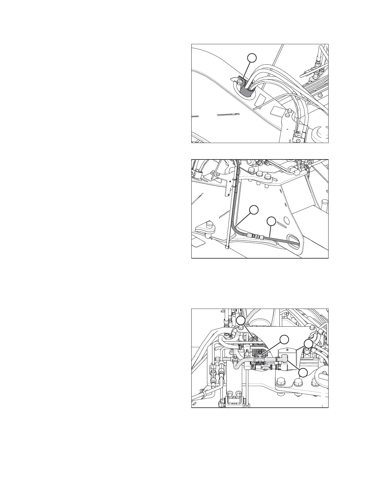
A
Figure 4.67: Lift Hoses
19. At rear of hitch, secure the hoses with adjustable
strap (A).
1022653
A
B
Figure 4.68: Lift Hoses
20. Connect hose (A) from left lift cylinder and hose (B)
(MD #224160 or MD #224162) at the hitch pivot.
4.8.4 Installing Electrical Components
Connecting Selector Valve and Transport Lighting Module
1022681
A
B
C
D
Figure 4.69: Selector Valve Supply
1. Locate plugs P102 (A) and P502 (B) on the transport
harness at the header end of the hitch. Route plugs
P102 (A) and P502 (B) towards selector valve (C).
2. Connect plug P502 (B) to the receptacle on selector
valve (C).
3. Connect plug P102 (A) to the upper input receptacle on
transport lighting module (D).
ASSEMBLING THE DISC MOWER (FACTORY-INSTALLED TRANSPORT)