214713 115 Revision A
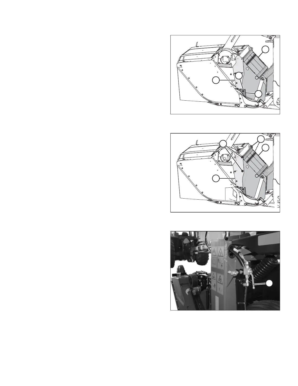
Figure 5.53: Left Side of Header (Right
Opposite)
4. Position shield (A) so that pins (B) engage the slots in
cutterbar support (C) and the bolt holes align with
panel (D).
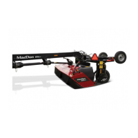
Figure 5.54: Left Side of Header (Right
Opposite)
5. Install four M16 hex head bolts (A), nuts, and flat
washers to secure shield (B) to the panel (C). Ensure
bolt heads face inboard.
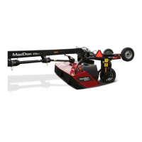
Figure 5.55: Lift Cylinder Lock-Out Valves
6. Open lift cylinder lock-out valves (A) on both sides of
the mower. Valve handles should be in the open
position (inline with the hose).
SETTING UP THE TRACTOR



 To Next Page