214713 49 Revision A
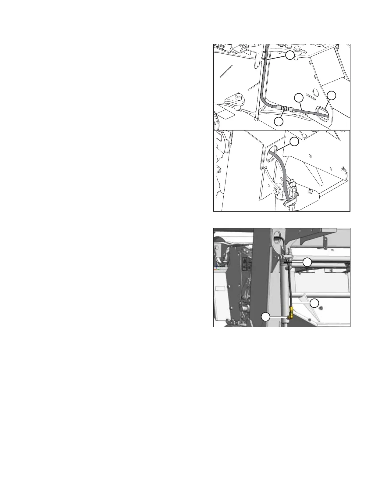
Figure 3.97: Lift Hose
28. Route hose (A) through opening (E) at the rear of
the frame.
29. Feed shortest hose (A) through opening (B) in carrier
frame as shown with male end (C) at the hitch pivot.
30. Connect hose (A) (MD #247106) and hose (D)
(MD #224160 or MD #224162) at the hitch pivot.
Figure 3.98: Lift Cylinder
31. Retrieve ORFS-6 x ORB-8 elbow from the
hardware bag.
32. Remove plug at base of lift cylinder and install elbow (A)
as shown.
33. Connect hose (B) to elbow and tighten.
34. Tighten remaining connection s.
35. Secure hose to cylinder with cable tie (C).
ASSEMBLING THE DISC MOWER (WITH OR WITHOUT THE DEALER-INSTALLED TRANSPORT)