214713 80 Revision A
1014334
A
B
C
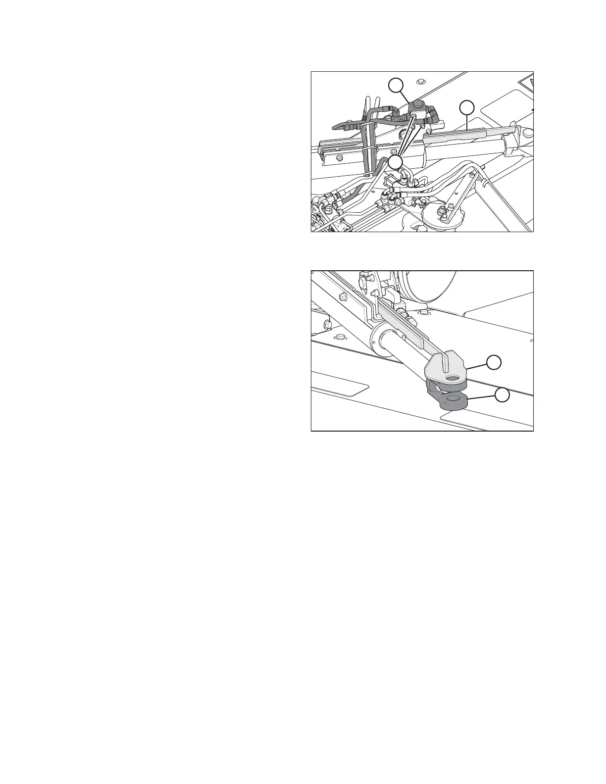
Figure 4.58: Alignment Control (Rear
Right View)
2. Check the travel of the cam arm (A) by sliding it in and
out of the cam assembly (B).
NOTE:
If the cam arm does not slide easily, loosen valve
mounting bolts (C), and slide the valve (B) up to the top
of the mounting holes. Retighten valve mounting
bolts (C).
1014337
A
B
Figure 4.59: Alignment Control (Rear
Right View)
3. Align the hole in the cam arm (A) with the hole in the
cylinder clevis (B).
ASSEMBLING THE DISC MOWER (FACTORY-INSTALLED TRANSPORT)