214713 86 Revision A
1015231
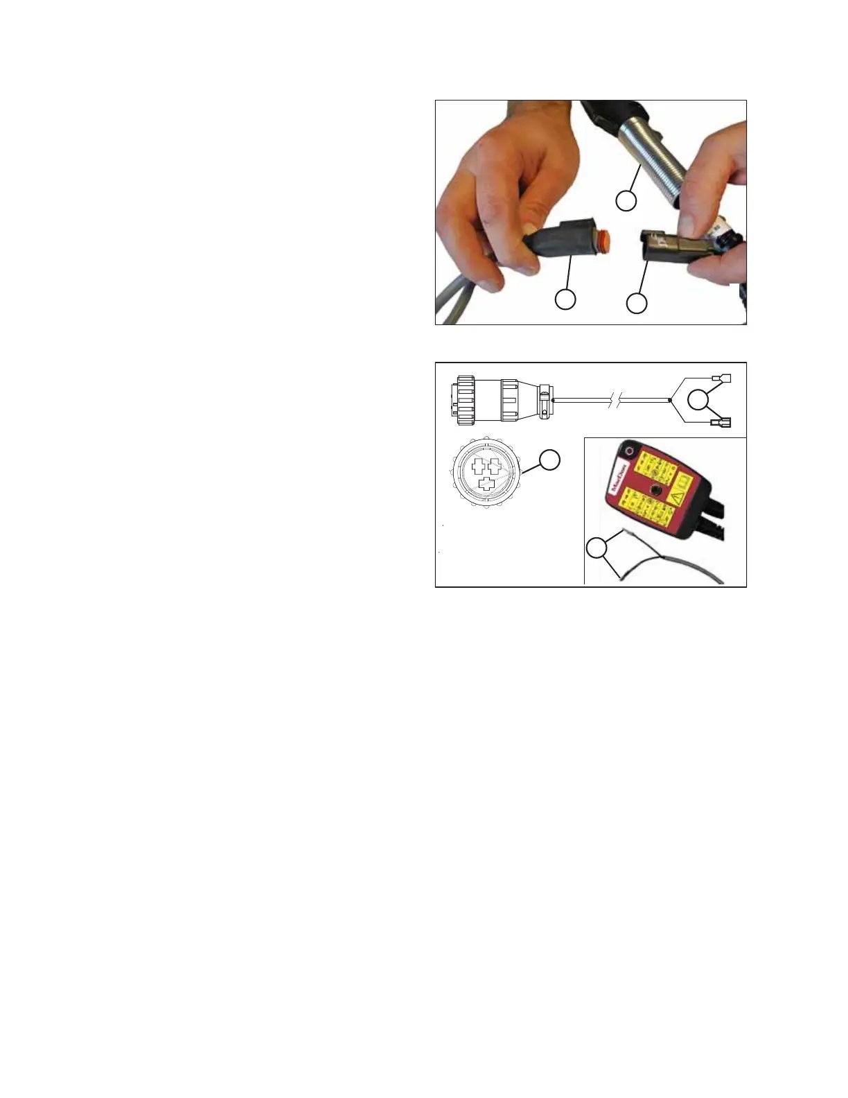
A
B
C
Figure 4.73: Transport Harness
3. Locate connector (C) that branches off the seven-pole
transport plug (A) and attach it to the remote wiring
harness (B).
10236931023693
A
B
C
Figure 4.74: Three-Pin Auxiliary Connector
4. If your tractor has a three-pin auxiliary power
connection:
NOTE:
The remote control has internal protection which
prevents damage caused by incorrect wiring, short
circuits, or overload conditions.
Connect two wires (B) from the three-pin auxiliary
connector (A) to the remote control wires (C) on the
remote control, wrap connections with electrical tape,
and proceed to Step 6, page 87.
• The wire with no tag connects to the tractor ground.
• The wire with the red tag connects to the
tractor power.
NOTE:
If connections are reversed, the lamp will not illuminate when the toggle switch is in field mode. Try the
following to correct the issue:
• Check internal fuse may have blown.
• Check for short in wires to solenoid valve on header.
• Check for incorrect wire connections (reversed) at the power supply or solenoid valve.
ASSEMBLING THE DISC MOWER (FACTORY-INSTALLED TRANSPORT)