214713 90 Revision A
10237071023720
A
B
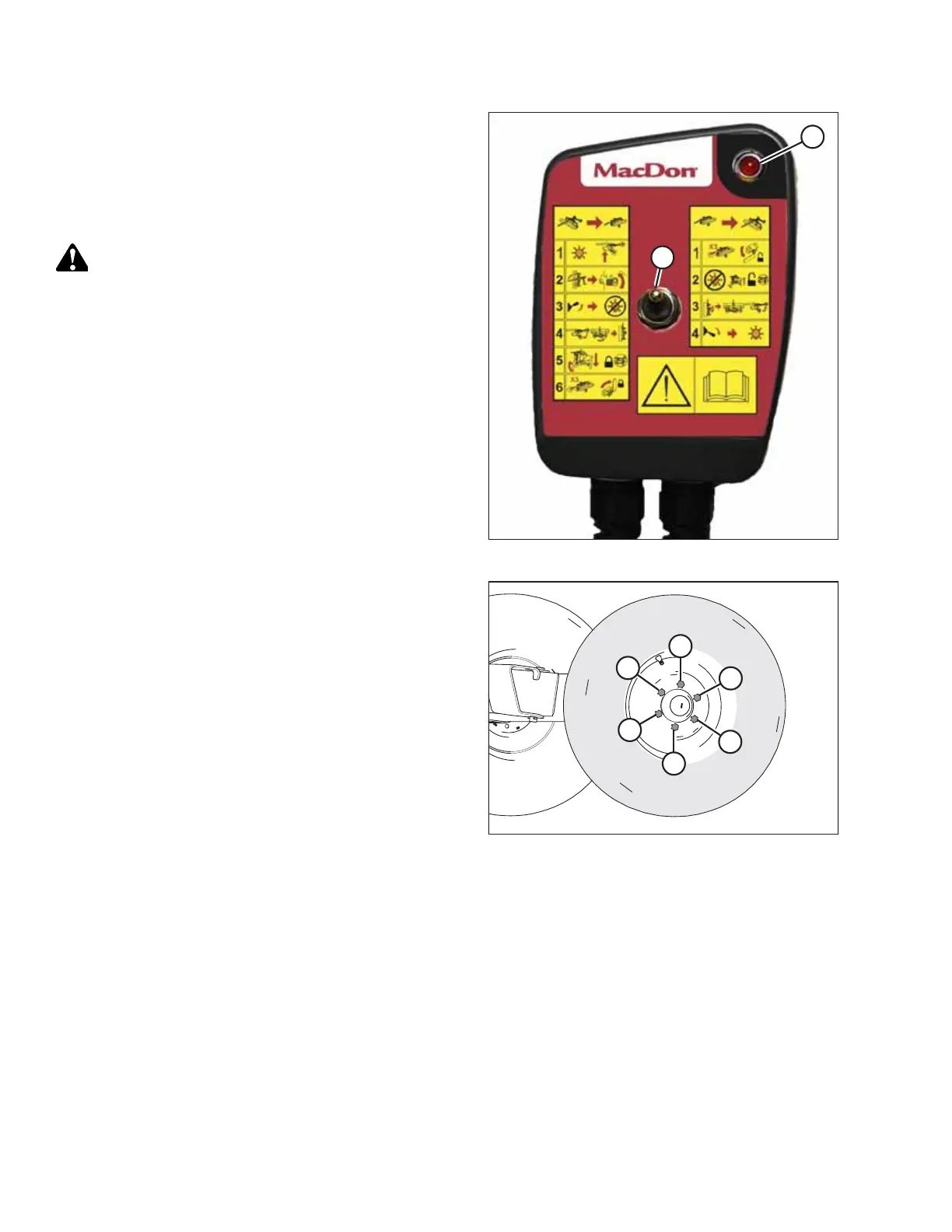
Figure 4.80: Transport Remote Control
7. In the cab, move transport switch to the upper
position (B) and ensure that light (A) is NOT illuminated.
The hitch swing circuit is now deactivated and the
transport circuit is active.
8. Using tractor’s hydraulics, raise the transport assembly
high enough to install the wheels.
CAUTION
When installing wheel, be sure to match countersunk
holes with bolt head profiles. Holes that are not
countersunk do NOT correctly seat the bolts.
1
2
3
4
5
6
1015147
Figure 4.81: Tightening Sequence
9. Retrieve transport wheels and install wheels with wheel
bolts. Ensure valve stem faces outboard. Do not fully
tighten bolts.
10. Lower wheels to the ground.
11. Torque wheel bolts to 160 Nm (120 lbf·ft) following the
tightening sequence shown.
NOTE:
Whenever a wheel is installed, check torque after one
hour of operation.
12. Check tire pressure and adjust as required. Refer to 7.2
Checking Tire Pressure, page 128.
ASSEMBLING THE DISC MOWER (FACTORY-INSTALLED TRANSPORT)