6-30
8. Start the engine again to raise the boom level, then stop the engine.
Now pull out the position pin (16) completely.
• To make the boom level, ensure that the boom angle display of the moment limiter indicates "0". In
addition, visually check the boom is level.
• The removed position pin (16) wiil be used later to connect the No.1 Fly-jib and the Fly-jib stowage
bracket A (21).
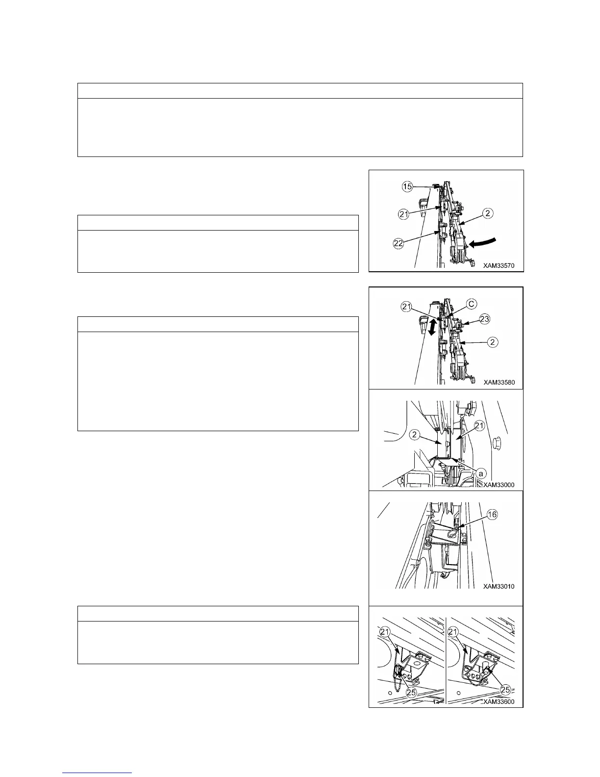
9. Turn the No.1 Fly-jib (2) around the position pin (15) on the right
side of the Main boom tip and stow it into the Fly-jib bracket A
(21) on the side face of the Main boom.
To turn the No.1 Fly-jib (2) around, drag the Fly-jib hook (10).
When the No.1 Fly-jib (2) turns too rapidly, hold the hook (10) to
stop turning.
10. Adjust the connection hole of No.1 Fly-jib (2) and hole (C) of
Fly-jib bracket A (21) .
• When you find it difficult to set the connection part of the No.1
Fly-jib (2) into the Fly-jib stowage bracket A (21), use the lever
block (23) again to provide a clearance (a) to facilitate that the
connection part of the No.1 Fly-jib (2) is set into the Fly-jib
stowage bracket A (21).
• When the connection hole of the No.1 Fly-jib (2) and hole (C) of
Fly-jib bracket A (21) do not correctly fit, telescope the Main
boom slowly to allow a correct fit.
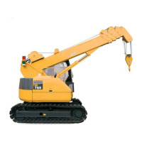
11. Once the connection hole of the No.1 Fly-jib (2) and the hole of
Fly-jib bracket A (21) are adjusted, insert the position pin (16) to
the hole then secure it with the linchpin (25).
Detach the linchpin (25) for the position pin (16) from the hole for
storage in the stowage bracket A (21) and apply to the position
pin (16).