MAN B&W 5.04
Page 1 of 3
MAN Diesel
198 79 36-7.0MAN B&W S50ME-B9
078 74 58-9.2.0
Engine room crane
Mass in kg including
lifting tools
Crane capacity in
tons selected
in accordance with
DIN and JIS
standard capacities
Crane
operating
width
in mm
Normal Crane
Height to crane hook in
mm for:
MAN B&W Double-Jib Crane
Normal
lifting
procedure
Reduced
height lifting
procedure
involving
tilting of main
components
(option)
Building-in height
in mm
Cylinder
cover
complete
with
exhaust
valve
Cylinder
liner with
cooling
jacket
Piston
with
rod and
stuffing
box
Normal
crane
MAN B&W
DoubleJib
Crane
A
Minimum
distance
H1
Minimum
height from
centre line
crankshaft
to centre line
crane hook
H2
Minimum height
from centre line
crankshaft to
centre line
crane hook
H3
Minimum
height from
centre line
crankshaft
to underside
deck beam
D
Additional height
required for
removal of exhaust
valve complete
without removing
any exhaust stud
Available on request
9,775 9,125 8,900
Available on request
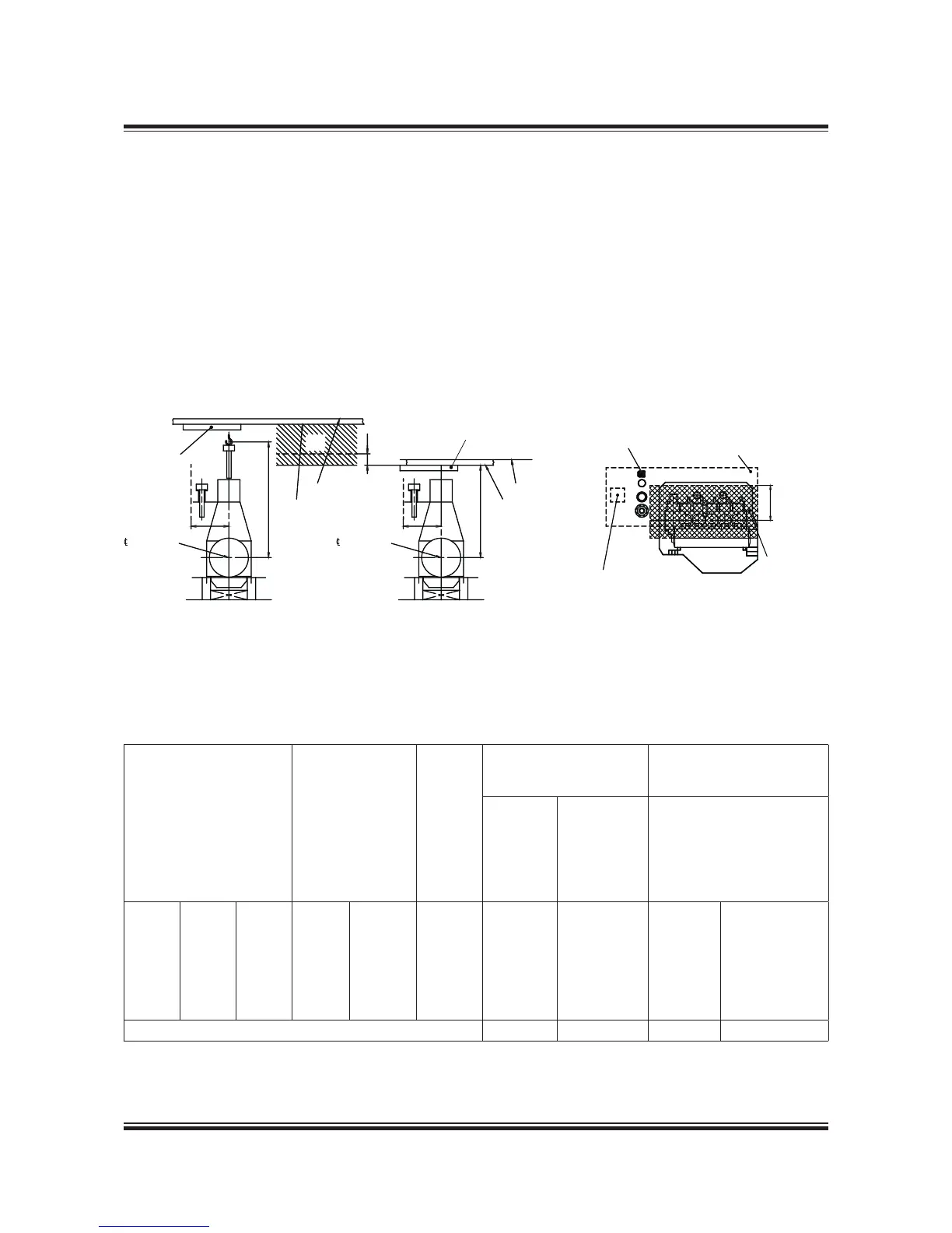
1) The lifting tools for the engine are designed to fit together with a standard crane hook with a lifting capacity in accordance with
the figure stated in the table. If a larger crane hook is used, it may not fit directly to the overhaul tools, and the use of an interme-
diate shackle or similar between the lifting tool and the crane hook will affect the requirements for the minimum lifting height in
the engine room (dimension H).
2) The hatched area shows the height where an MAN B&W Double-Jib Crane has to be used.
The crane hook travelling area must cover at least
the full length of the engine and a width in accord-
ance with dimension A given on the drawing (see
cross-hatched area).
It is furthermore recommended that the engine
room crane can be used for transport of heavy
spare parts from the engine room hatch to the
spare part stores and to the engine.
See example on this drawing.
The crane hook should at least be able to reach
down to a level corresponding to the centre line of
the crankshaft.
For overhaul of the turbocharger(s), trolley mount-
ed chain hoists must be installed on a separate
crane beam or, alternatively, in combination with
the engine room crane structure, see separate
drawing with information about the required lifting
capacity for overhaul of turbochargers.
Normal crane
Crankshaft
Deck beam
A A
A
1)
H1/H2
2)
Deck
Deck beam
H3
D
Deck
Crankshaft
MAN B&W Doublejib Crane
Recommended area to be covered
by the engine room crane
Spares
Engine room hatch
Minimum area
to be covered
by the engine
room crane
519 24 62-8.0.0
Fig. 5.04.01: Engine room crane
 Loading...


