Example 3: Special running conditions.
Engine coupled to fixed pitch propeller (FPP) and with shaft generator
M Specified MCR of engine
S Continuous service rating of engine
MP Specified MCR for propulsion
SP Continuous service rating of propulsion
SG Shaft generator
Point M of the load diagram is found:
Line 1 Propeller curve through point S
Point M Intersection between line 1 and line L
1
– L
3
178 06 351.9
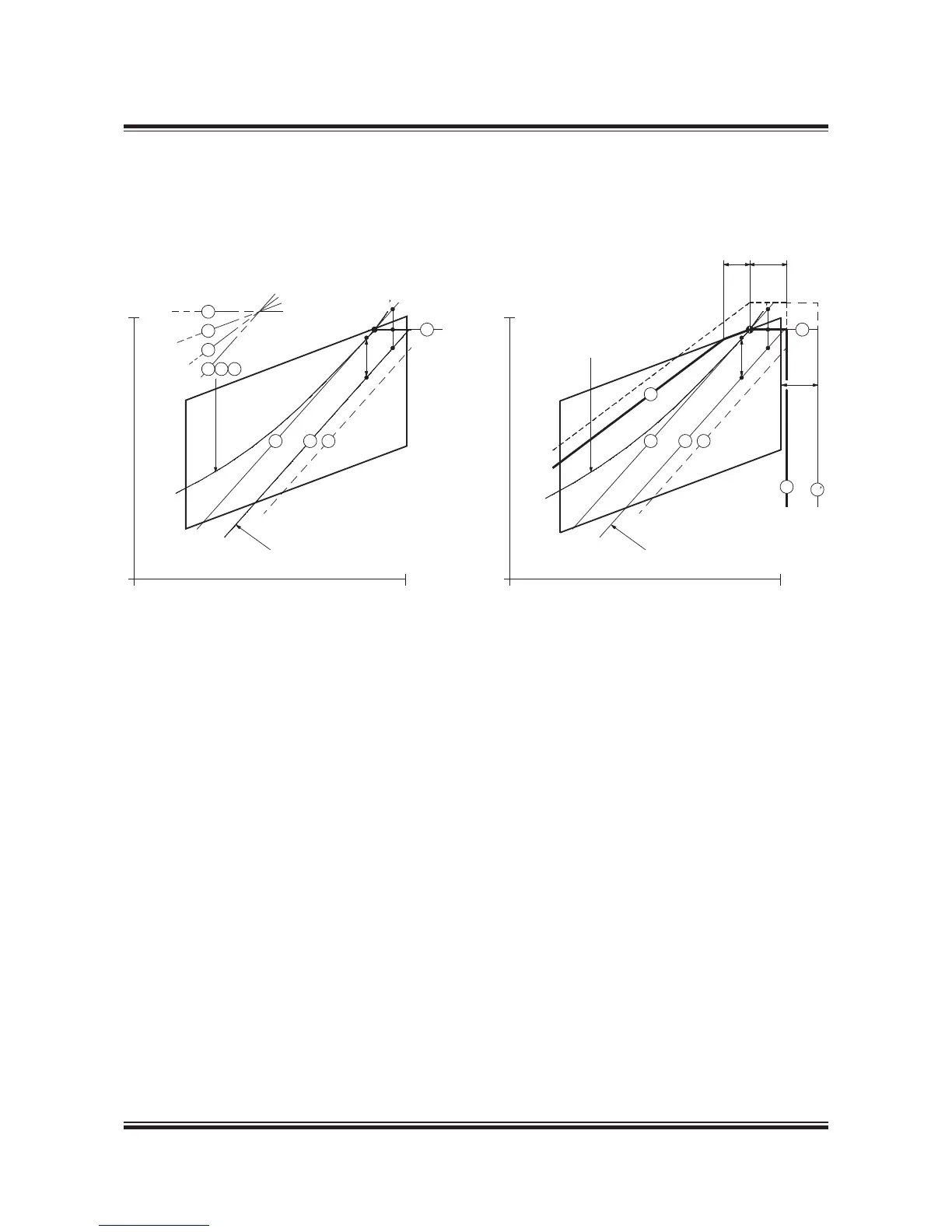
Also for this special case in example 3, a shaft generator is installed but, compared to example 2, this case has a specified MCR for
propulsion, MP, placed at the top of the layout diagram.
This involves that the intended specified MCR of the engine M’ will be placed outside the top of the layout diagram.
One solution could be to choose a larger diesel engine with an extra cylinder, but another and cheaper solution is to reduce the
electrical power production of the shaft generator when running in the upper propulsion power range.
In choosing the latter solution, the required specified MCR power can be reduced from point M’ to point M as shown. Therefore,
when running in the upper propulsion power range, a diesel generator has to take over all or part of the electrical power production.
However, such a situation will seldom occur, as ships are rather infrequently running in the upper propulsion power range.
Point M, having the highest possible power, is then found at the intersection of line L
1
– L
3
with line 1 and the corresponding load
diagram is drawn.
 Loading...


